
High-uniformity paint spraying facility

A paint spraying equipment and technology of uniformity, applied in the field of shell surface spraying equipment, can solve the problems of the protective effect of the protective layer on the appearance of products, uneven spraying, inconvenient use, etc., to avoid shaking, ensure the spraying effect, and avoid the effect of emptying

Inactive Publication Date: 2021-05-04
新印科技股份有限公司
View PDF10 Cites 0 Cited by
  • Summary
  • Abstract
  • Description
  • Claims
  • Application Information

AI Technical Summary

Problems solved by technology

[0003] Most of the existing protective layers are laid by spraying paint, which is not only low in cost, but also easy to use, and is suitable for coating the outer surface of heterogeneous structures. However, most of the existing shells are between Send the shell products one by one to the location of the painting assembly for continuous spraying, often due to the irregular structure of the shell, the shell shakes during the painting process, resulting in uneven spraying, which will affect the protective effect of the protective layer and the appearance of the product. Great impact, not easy to use

Method used


Image

  • High-uniformity paint spraying facility
  • High-uniformity paint spraying facility
  • High-uniformity paint spraying facility

Examples


Embodiment Construction

[0028]In order to make the object, technical solution and advantages of the present invention clearer, the present invention will be further described in detail below in conjunction with the accompanying drawings and embodiments. It should be understood that the specific embodiments described here are only used to explain the present invention, and are not intended to limit the present invention, that is, the described embodiments are only some of the embodiments of the present invention, but not all of the embodiments. The components of the embodiments of the invention generally described and illustrated in the figures herein may be arranged and designed in a variety of different configurations.

[0029] Accordingly, the following detailed description of the embodiments of the invention provided in the accompanying drawings is not intended to limit the scope of the claimed invention, but merely represents selected embodiments of the invention. Based on the embodiments of the ...


PUM


Abstract

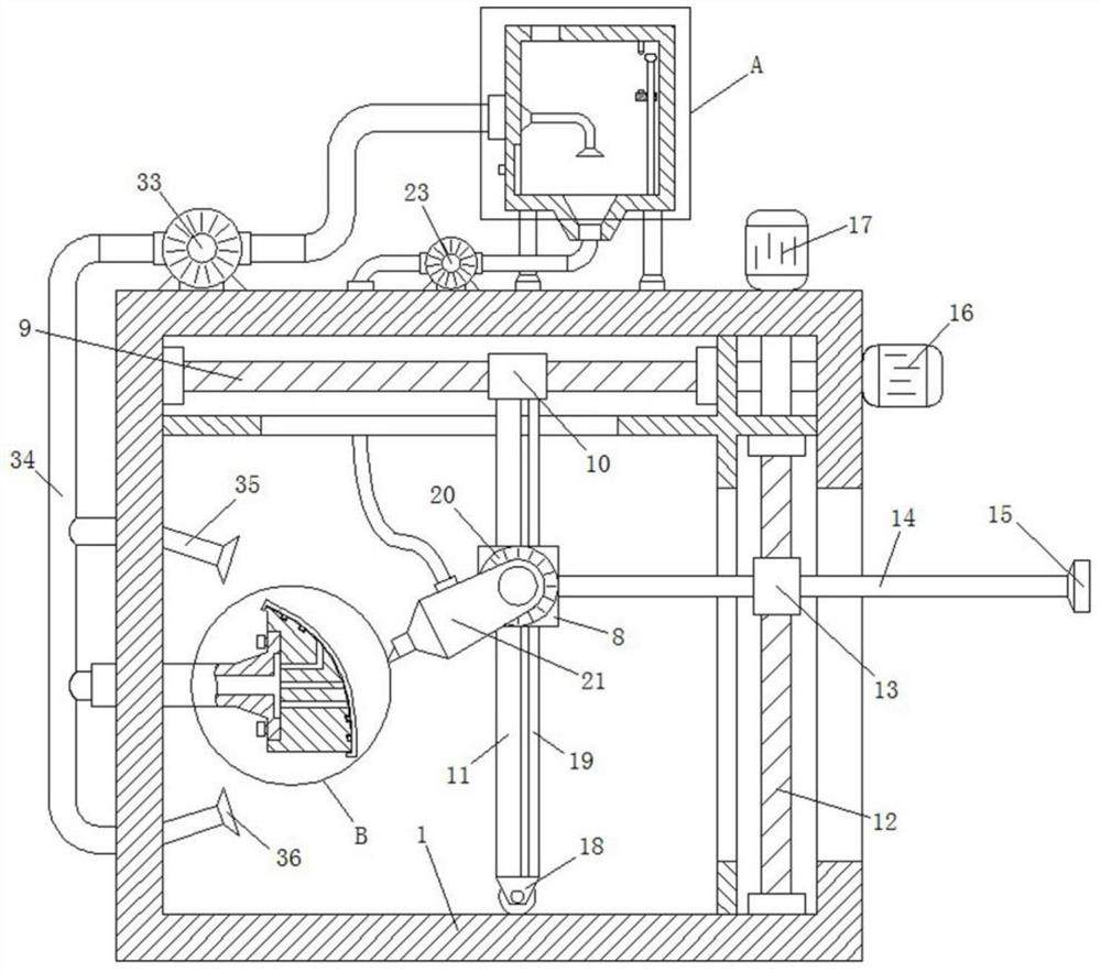
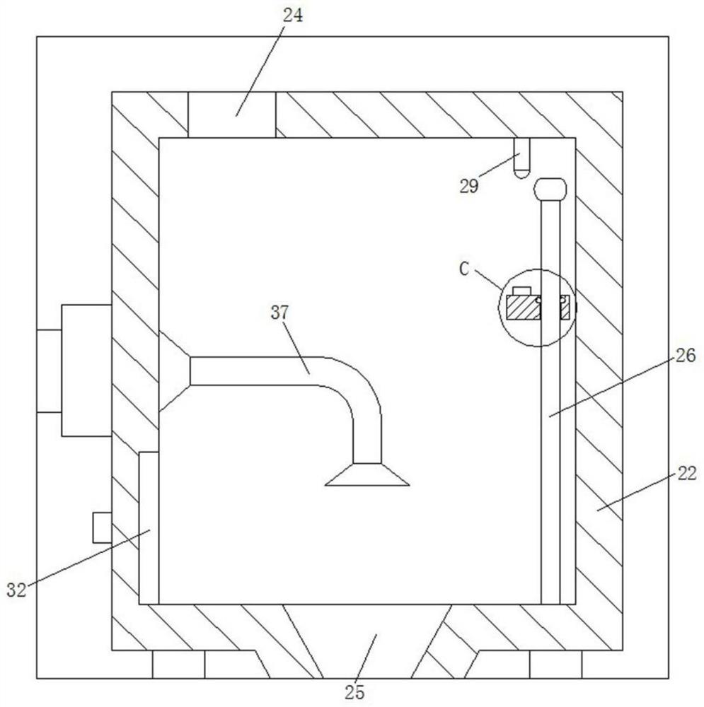
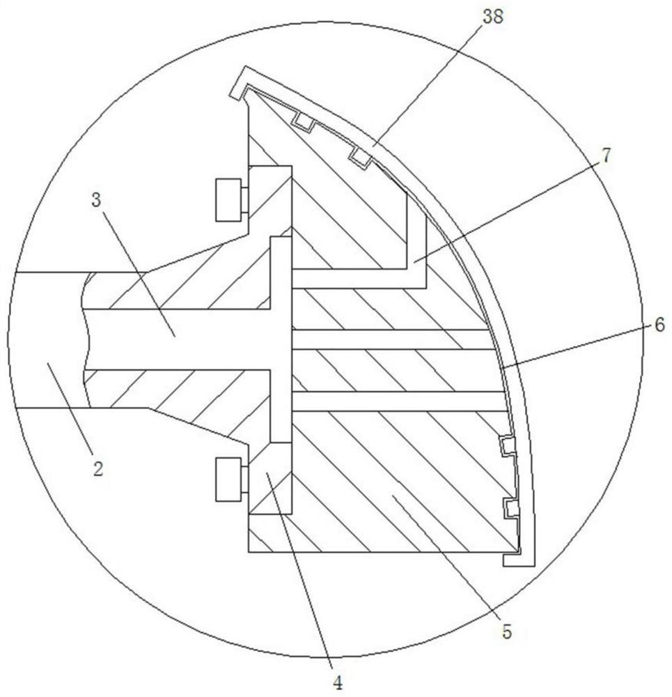
The invention discloses a high-uniformity paint spraying facility which comprises a paint spraying chamber. A positioning base is arranged on the side wall of the paint spraying chamber, an absorption pipeline is arranged inside the positioning base, a mounting head is arranged at one end of the positioning base, and the other end of the positioning base penetrates through the paint spraying chamber to be fixedly arranged. A mounting block is fixedly arranged on the mounting head, a mounting surface which is matched with the hidden surface of a shell to be painted is arranged on the mounting block, and a negative pressure pipeline which communicates with the mounting surface and the absorption pipeline is further arranged on the mounting block. The paint spraying facility further comprises a negative pressure device which communicates with the absorption pipeline. According to the scheme, by means of the arrangement of the mounting head and the mounting block on the positioning base, the shell to be painted can be fixed, and the hidden surface of the shell is connected with the mounting block; and meanwhile, by means of the arrangement of the negative pressure device and the absorption pipeline, the negative pressure is generated to tightly absorb a shell product to the mounting block, and therefore the stability of the product in the spraying process is guaranteed, the product is prevented from shaking, and the spraying effect can be guaranteed.

Description

technical field [0001] The invention relates to the technical field of shell surface spraying equipment, in particular to a high-uniformity spraying equipment. Background technique [0002] Existing production equipment, printing equipment, means of transportation, household appliances and even toys and other products usually have a protective layer on their shells, which can not only protect the items from moisture and heat insulation, but also greatly improve the aesthetic performance of the items. [0003] Most of the existing protective layers are laid by spraying paint, which is not only low in cost, but also easy to use, and is suitable for coating the outer surface of heterogeneous structures. However, most of the existing shells are between Send the shell products one by one to the location of the painting assembly for continuous spraying. Due to the irregular structure of the shell, the shell shakes during the painting process, resulting in uneven spraying, which wi...

Claims


Application Information

Patent Timeline
Patent Type & Authority Applications(China)
IPC IPC(8): B05B16/00B05B13/02B05B15/20B05B15/68G01B11/14G01F23/56
CPCB05B13/02B05B15/20B05B15/68B05B16/00G01B11/14G01F23/56
Inventor 不公告发明人
Owner 新印科技股份有限公司
Learn More