
Lining structure of steel ladle for steelmaking emergency and building method of lining structure

A ladle and inner lining technology, which is applied to the inner lining structure and masonry field of steel ladles for emergency use in steelmaking, and can solve problems such as the complexity of the molten steel process

Pending Publication Date: 2021-05-04
广西钢铁集团有限公司 +2
View PDF0 Cites 0 Cited by
  • Summary
  • Abstract
  • Description
  • Claims
  • Application Information

AI Technical Summary

Problems solved by technology

[0004] Therefore, the technical problem to be solved by the present invention is to overcome the defect that the emergency ladle structure in the prior art is simple, which makes the process of processing the molten steel cooled in the emergency ladle complicated, thereby providing a steelmaking emergency ladle lining structure and its construction. construction method

Method used


Image

  • Lining structure of steel ladle for steelmaking emergency and building method of lining structure
  • Lining structure of steel ladle for steelmaking emergency and building method of lining structure
  • Lining structure of steel ladle for steelmaking emergency and building method of lining structure

Examples


Embodiment 1

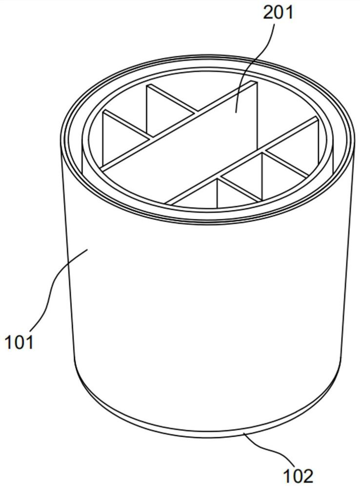
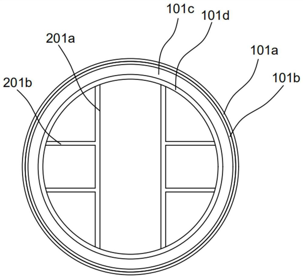
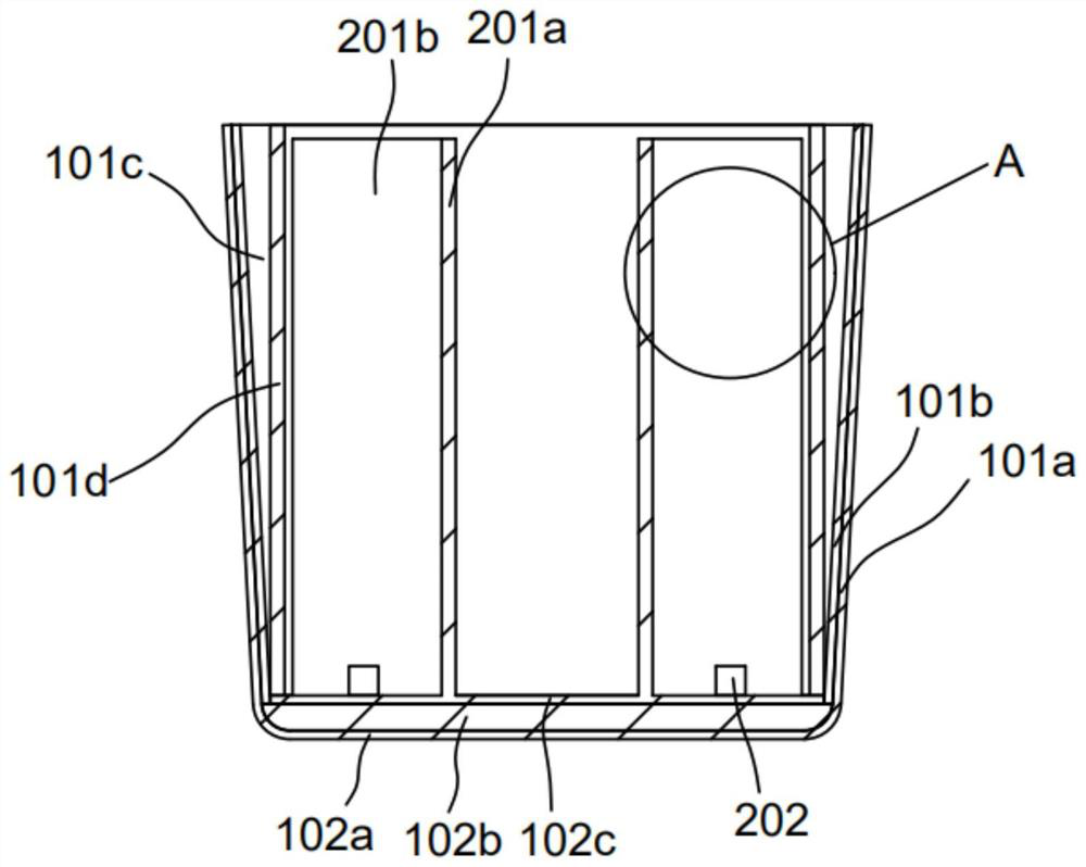
[0027] This embodiment provides a lining structure for steel-making emergency ladles, such as Figure 1-4 shown, including,

[0028] The ladle 100 includes a cladding wall structure 101 and a cladding bottom structure 102 arranged at the bottom of the cladding wall structure 101 ;

[0029] The cladding structure 101 includes a cladding 101a with a U-shaped axial longitudinal section. A permanent shell layer 101b is placed close to the inside of the cladding 101a. A working shell layer 101d is set inside the permanent shell layer 101b. The permanent shell layer 101b There is a gap 101c between the shell working layer 101d, the distance between the gap 101c is 0-170mm, and the gap 101c is filled with magnesia filler; the shell permanent layer 101b is made of 110mm thick high-alumina castable; the shell working layer 101d is made of 100mm Thick arc-shaped high-alumina brick masonry; the bottom cladding structure 102 includes a bottom shell 102a, a bottom permanent layer 102b is ...

Embodiment 2

[0035] A kind of masonry method for the inner lining structure of steel-making emergency ladle, such as Figure 1-4 shown, including,

[0036] S1: On the basis of the cladding and the bottom shell, the permanent layer of the shell and the bottom permanent layer are vibrated with high-alumina castables, and baked after construction;

[0037] S2: The working layer of the shell and the bottom working layer are constructed with high-alumina bricks, and the gap between the working layer of the shell and the permanent layer of the shell is filled while the working layer of the shell is being constructed;

[0038] S3: The prefabricated unit is built with aluminum-magnesium refractory mud inside the ladle to form a "well"-shaped prefabricated part;

[0039] S4: leave it for 24 hours naturally.

[0040] For the construction of the permanent layer of the shell, high-alumina castables are used for vibration construction, and the amount of water added is 7.5% of the mass of the castable...


PUM

PropertyMeasurementUnit
Densityaaaaaaaaaa
Compressive strengthaaaaaaaaaa
Densityaaaaaaaaaa

Abstract

The invention provides a lining structure of a steel ladle for steelmaking emergency and a building method of the lining structure. The lining structure comprises the steel ladle and a lining structure body, and the steel ladle comprises a ladle wall structure and a ladle bottom structure arranged at the bottom of the ladle wall structure; and the lining structure body comprises a #-shaped prefabricated part arranged in the interior of the ladle wall structure. A cooled steel block in the emergency steel ladle is convenient to pour out, oxygen cutting is carried out along a molten steel overflow port of an aluminum-magnesium precast block, the steel block can be easily divided into seven steel blocks, during division, the gas consumption is small, consumed time is short, cutting is convenient, the steel blocks are hoisted by adopting a traveling crane and are easy to carry, and the requirement of large-tonnage steel ladle steelmaking can be met.

Description

technical field [0001] The invention relates to the technical field of metallurgy, in particular to an inner lining structure of a steel ladle for emergency use in steelmaking and a masonry method thereof. Background technique [0002] Steelmaking emergency ladle refers to the spare ladle that is used as an emergency ladle or used as a centralized collection and treatment of molten steel / hot metal in the event of an accident in the steelmaking area. After entering the ladle, the continuous casting machine breaks down, and the molten steel in the ladle cannot be poured, so the molten steel can be poured into the emergency ladle, and it is convenient to handle after cooling. The ladle does not participate in the normal steelmaking operation, and is only used as a temporary container and storage of molten steel. The high-temperature molten steel is cooled in the steelmaking emergency ladle to form a large steel column or a large steel block. The emergency ladle is turned over t...

Claims


Application Information

Patent Timeline
IPC IPC(8): B22D41/02B22D41/04
CPCB22D41/02B22D41/023B22D41/04
Inventor 李源源刘远顾琛余辉陈梁沈明科陆志坚文震陈峰刘光平魏国平陶群金潘剑男赵忠阳潘小勇
Owner 广西钢铁集团有限公司
Learn More