
Supercritical carbon dioxide injection device for thick oil mechanism experiment

A carbon dioxide and injection device technology, which is applied in the direction of mechanical equipment, production fluid, wellbore/well components, etc., can solve the problems of slow feedback, limited gas volume, and inability to output gas in time

Active Publication Date: 2021-05-04
XI AN JIAOTONG UNIV
View PDF6 Cites 1 Cited by
  • Summary
  • Abstract
  • Description
  • Claims
  • Application Information

AI Technical Summary

Problems solved by technology

At present, the existing method is to press the gas pressurized from the gas cylinder into the intermediate piston container again, and then inject carbon dioxide into the follow-up device through the other side of the piston container. The structure limits the pressure injection, and there are the following disadvantages: 1. The volume of the piston container is limited, and the volume of stored compressed gas is limited, which is difficult to meet the requirements of long-term experiments; 2. The feedback is slow, and the compression coefficient of water and carbon dioxide is greatly different. The fluctuation of back pressure will cause the gas to fail to output in time; 3. Use the middle piston The container is pressurized gas, the pressure upper limit is low, and the experimental research under the condition of high pressure parameters cannot be completed

Method used


Image

  • Supercritical carbon dioxide injection device for thick oil mechanism experiment

Examples


Embodiment Construction

[0026] The present invention is described in further detail below in conjunction with accompanying drawing:

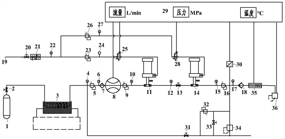
[0027] Such as figure 1 As shown, a supercritical carbon dioxide injection device for heavy oil mechanism experiment, including driving gas source injection device, air flow control device, safety protection device and control system 29;

[0028] The driving gas source injection device is connected with a first gas booster pump 11 and a second gas booster pump 14. The gas source input end of the first gas booster pump 11 and the gas source input end of the second gas booster pump 14 are all connected to Power compressed air source 19, shut-off valve and pressure gauge are arranged between the first gas booster pump 11 and power compressed air source 19, shut-off valve and pressure gauge are arranged between the second gas booster pump 14 and power compressed air source 19. surface;

[0029] The air flow control device includes a carbon dioxide gas source 1, a constan...


PUM


Abstract

The invention discloses a supercritical carbon dioxide injection device for a thick oil mechanism experiment. The supercritical carbon dioxide injection device comprises a drive gas source injection device, a gas flow control device, a safety protection device and a control system, wherein output ends of a first gas booster pump and a second gas booster pump which are independently arranged are connected in series, and the gas inlet ends of the first gas booster pump and the second gas booster pump are provided with stop valves, pressure gauges and flow proportional valves, so that the first gas booster pump and the second gas booster pump are controlled simultaneously, and the boosting efficiency and precision are improved; and a constant-temperature water bath with a preset temperature is set, then flow metering and pressurization are conducted, so that the problem that the mass metering error is large due to phase change of carbon dioxide in the pressurization process is effectively solved, continuous and stable small-flow supercritical carbon dioxide output can be achieved, and the constant-flow constant-pressure constant-temperature output function is achieved. The supercritical carbon dioxide injection device has the advantages of being easy to operate, safe, reliable and the like, meets the requirement for indoor thick oil mechanism research based on carbon dioxide, can achieve precise control and feedback through a control system, and improves the control precision.

Description

technical field [0001] The invention relates to a supercritical carbon dioxide injection device used for heavy oil mechanism experiments, which can continuously and stably output small-flow supercritical carbon dioxide, and is used for carbon dioxide miscible flooding research or carbon dioxide-assisted supercritical water heavy oil thermal recovery research, which belongs to petroleum Fields of engineering and process technology. Background technique [0002] The resources suitable for the development of carbon dioxide in the world are 300 billion to 600 billion barrels. Compared with other oil displacement technologies, carbon dioxide flooding has the characteristics of wide application range, low oil displacement cost and high recovery rate. It can not only meet the needs of oilfield development, but also It can also solve the problem of carbon dioxide sequestration. Due to the limited platform space and short service life of offshore heavy oil platforms, supercritical m...

Claims


Application Information

Patent Timeline
Patent Type & Authority Applications(China)
IPC IPC(8): F17D1/02F17D3/01F17D3/18E21B43/16
CPCE21B43/164F17D1/02F17D3/01F17D3/18
Inventor 郭烈锦黄祖杰赵秋阳陈磊王晔春苗岩董宇谢天
Owner XI AN JIAOTONG UNIV
Learn More