Eureka AIR delivers breakthrough ideas for toughest innovation challenges, trusted by R&D personnel around the world.

Vertical electrical automation equipment and mounting mechanism thereof

A technology for installing mechanisms and equipment, which is applied to electrical equipment casings/cabinets/drawers, electrical components, mechanical equipment, etc., and can solve problems such as water accumulation on the ground, poor waterproof performance of vertical electrical automation equipment, troubles, etc.

Pending Publication Date: 2021-05-04
滁州市凌山电气设备有限公司
View PDF0 Cites 2 Cited by
  • Summary
  • Abstract
  • Description
  • Claims
  • Application Information

AI Technical Summary

Problems solved by technology

[0003] Vertical electrical automation equipment is also used in existing building construction. The existing vertical electrical automation equipment is basically fixed installation. It is troublesome when the device needs to be moved. Manpower and material resources affect the construction process, and the waterproof performance of vertical electrical automation equipment is poor. The general environment of the construction site is relatively complicated. Construction personnel perform maintenance when it rains. If the maintenance is not timely, the rainwater will enter the interior of the vertical electrical automation equipment, which will easily lead to short circuit and burnout of the equipment, and in serious cases, it will easily cause safety accidents. Therefore, those skilled in the art have provided a vertical electrical automation equipment. Automation equipment and its installation mechanism, to solve the problems raised in the above-mentioned background technology

Method used


Image

  • Vertical electrical automation equipment and mounting mechanism thereof
  • Vertical electrical automation equipment and mounting mechanism thereof
  • Vertical electrical automation equipment and mounting mechanism thereof

Examples


Embodiment Construction

[0036]Next, the technical solutions in the embodiments of the present invention will be described in contemplation in the embodiment of the present invention, and it is apparent that the described embodiments are merely the embodiments of the present invention, not all of the embodiments. Embodiments in the present invention, those of ordinary skill in the art will belong to the scope of the present invention in all other embodiments obtained without making creative labor.

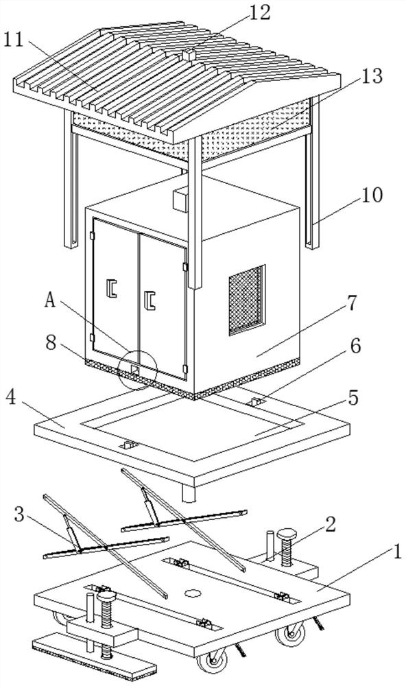
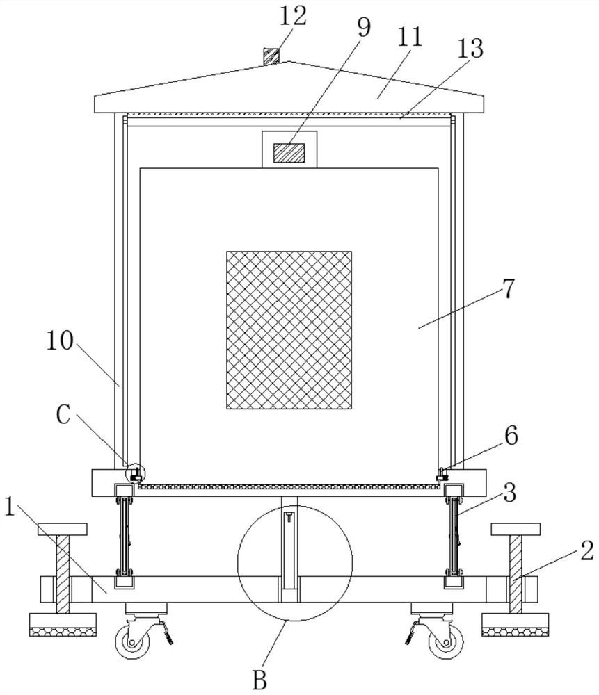
[0037]SeeFigure 1-10In the embodiment of the present invention, a construction mounting mechanism and a mounting mechanism thereof include a bottom plate 1, a front side and back surface of the bottom plate 1, and a fixed assembly 2, and the top sliding connection of the bottom plate 1 is two or more. The lifting assembly 3, the top of the lifting assembly 3 slides the mounting plate 4, the top of the mounting plate 4 is opened, and the bottom portion of the mounting plate 4 is fixedly connected to the liquid level...


PUM


Abstract

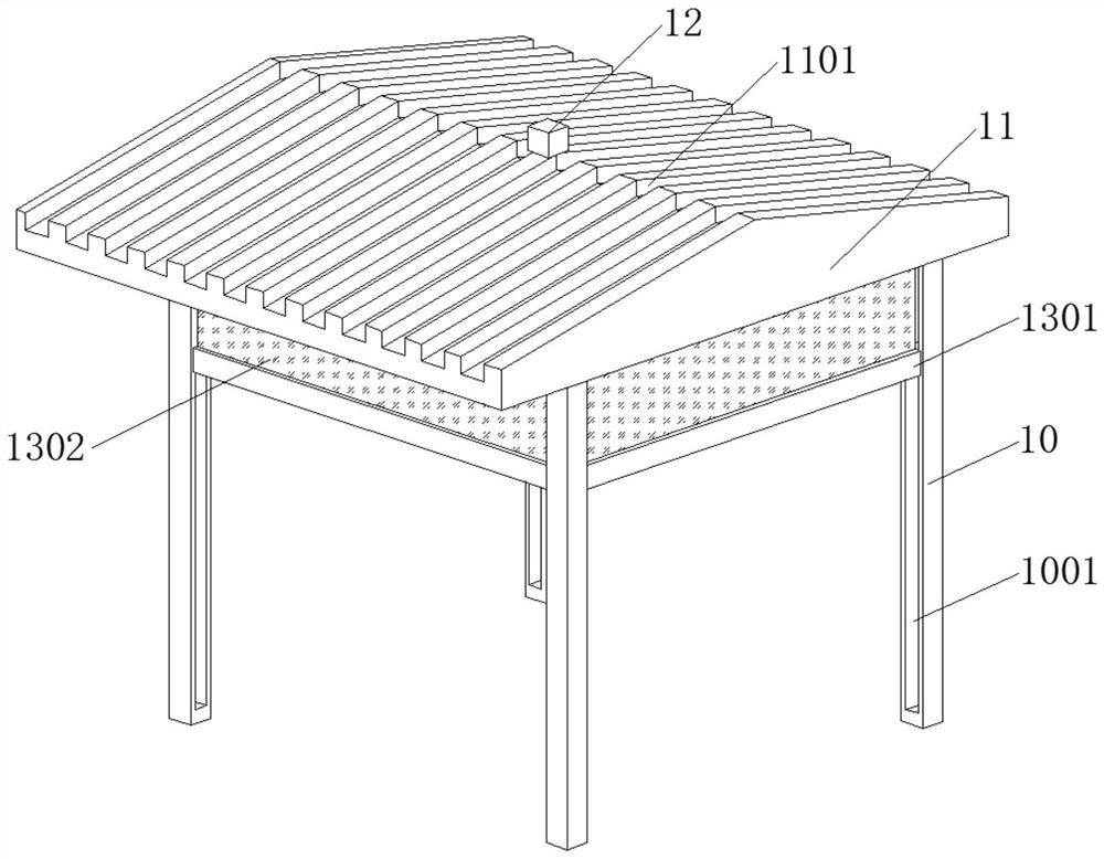
The invention discloses a construction mounting mechanism. The mounting mechanism comprises a bottom plate, the top of the bottom plate is connected with a lifting assembly, the top of the lifting assembly is connected with a mounting plate, the top of the mounting plate is provided with mounting grooves, and the mounting plate is internally provided with at least two clamping assemblies. And the clamping assemblies penetrate through the mounting grooves and extend into the mounting grooves, the top of the mounting plate is fixedly connected with a plurality of supporting rods, and the tops of the supporting rods are fixedly connected with protective eaves. A liquid level communicating pipe is fixedly connected to the bottom of the mounting plate, a liquid level sensor is arranged on the inner top wall of the liquid level communicating pipe, the liquid level communicating pipe penetrates through the bottom plate, and an opening of the liquid level communicating pipe faces downwards and communicates with the outside. Through arranging a protection assembly,all-directional rain and snow prevention can be carried out on a device, so the rain and snow are prevented form permeating into the device; and meanwhile, a liquid level sensor and a controller are matched with each other, so that the protection performance of the device is improved, when water is accumulated on the ground, the device can automatically ascend and descend, and the situation that water enters the device is avoided.

Description

Technical field[0001]The present invention relates to the technical field of electrical automation equipment, and more particularly to a vertical electrical automation device and its mounting mechanism.Background technique[0002]Electrical engineering and its automation are an emerging discipline in the field of electrical information, but since people's daily lives and industrial production are closely related, the development is very rapid, and now it is relatively mature, and has become an important part of high-tech industries. Applications in the fields of industrial, agriculture, defense, play an increasingly important role in the national economy, and its tentacles extend to all walks of life, small to a switch design, and the research of the aerospace plane has its figure. This professional is able to engage in system operations related to electrical engineering, automatic control, power electronic technology, information processing, test technology, development, economic man...

Claims


Application Information

Patent Timeline
Patent Type & Authority Applications(China)
IPC IPC(8): G05B19/04G01W1/00G01F23/00H05K5/02
CPCG01F23/00G01W1/00G05B19/04H05K5/0234
Inventor 路德荣
Owner 滁州市凌山电气设备有限公司
Why Eureka
Eureka Blog
Learn More