Stamping and bending device for sheet metal machining

A punching, bending and sheet metal technology, applied in metal processing equipment, feeding devices, positioning devices, etc., can solve the problems of pressure influence, low work efficiency, and physical exertion under the bending effect.

Pending Publication Date: 2021-05-07
龚安国
View PDF8 Cites 0 Cited by
  • Summary
  • Abstract
  • Description
  • Claims
  • Application Information

AI Technical Summary

Problems solved by technology

[0006] In order to overcome the disadvantages that the current manual operation equipment needs to consume a lot of physical strength when stamping and bending sheet metal, the work efficiency is low, and the bending effect will be affected by the force of the worker. The technical problem of the present invention is: to provide automatic Stamping and bending device for sheet metal processing with precise bending and safe operation

Method used


Image

  • Stamping and bending device for sheet metal machining
  • Stamping and bending device for sheet metal machining
  • Stamping and bending device for sheet metal machining

Examples


Embodiment 1

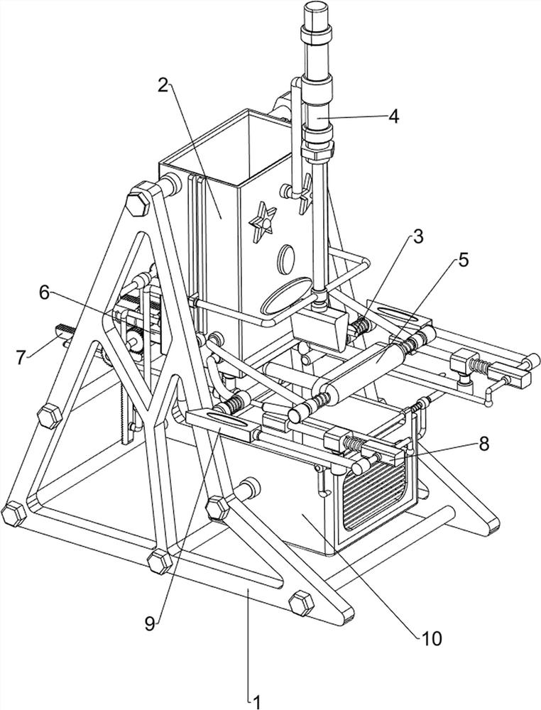
[0077] A stamping and bending device for sheet metal processing, such as figure 1 As shown, it includes a base 1, a discharge frame 2, a retaining column 3, an extrusion mechanism 4, a discharge mechanism 5 and a push mechanism 6. The upper part of the base 1 is provided with a discharge frame 2, and the right side of the lower part of the discharge frame Front and rear symmetry is provided with retaining column 3, discharge frame 2 is provided with extruding mechanism 4, discharge frame 2 is provided with discharge mechanism 5, and discharge frame 2 is provided with pusher mechanism 6.

[0078] When the sheet metal needs to be stamped and bent, the sheet metal is first put into the discharge frame 2, and then people manually pull the sheet metal onto the retaining column 3, so that the retaining column 3 blocks the sheet metal from falling, and at the same time people Rotate the discharging mechanism 5 upwards to the position that blocks the sheet metal, so that the sheet met...

Embodiment 2

[0080] On the basis of Example 1, such as figure 2 , image 3 and Figure 4 As shown, the extrusion mechanism 4 includes a support frame 41, a cylinder 42, a piston rod 43 and an extruding block 44. The right side of the upper part of the discharge frame 2 is provided with a support frame 41, and the upper part of the support frame 41 is provided with a cylinder 42. The cylinder 42 is telescopic. A piston rod 43 is arranged on the rod, and an extrusion block 44 is arranged at the bottom of the piston rod 43 .

[0081] When extruding the sheet metal, people first start the cylinder 42, and the extension of the telescopic rod of the cylinder 42 drives the piston rod 43 to move downward, and then drives the extrusion block 44 to move downward, and then performs extrusion operation on the sheet metal below, so that the sheet metal When it is bent, the telescopic rod of the cylinder 42 drives the piston rod 43 to move upward when retracting, and then drives the extrusion block 4...

Embodiment 3

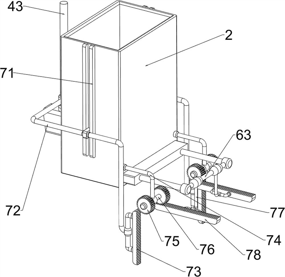
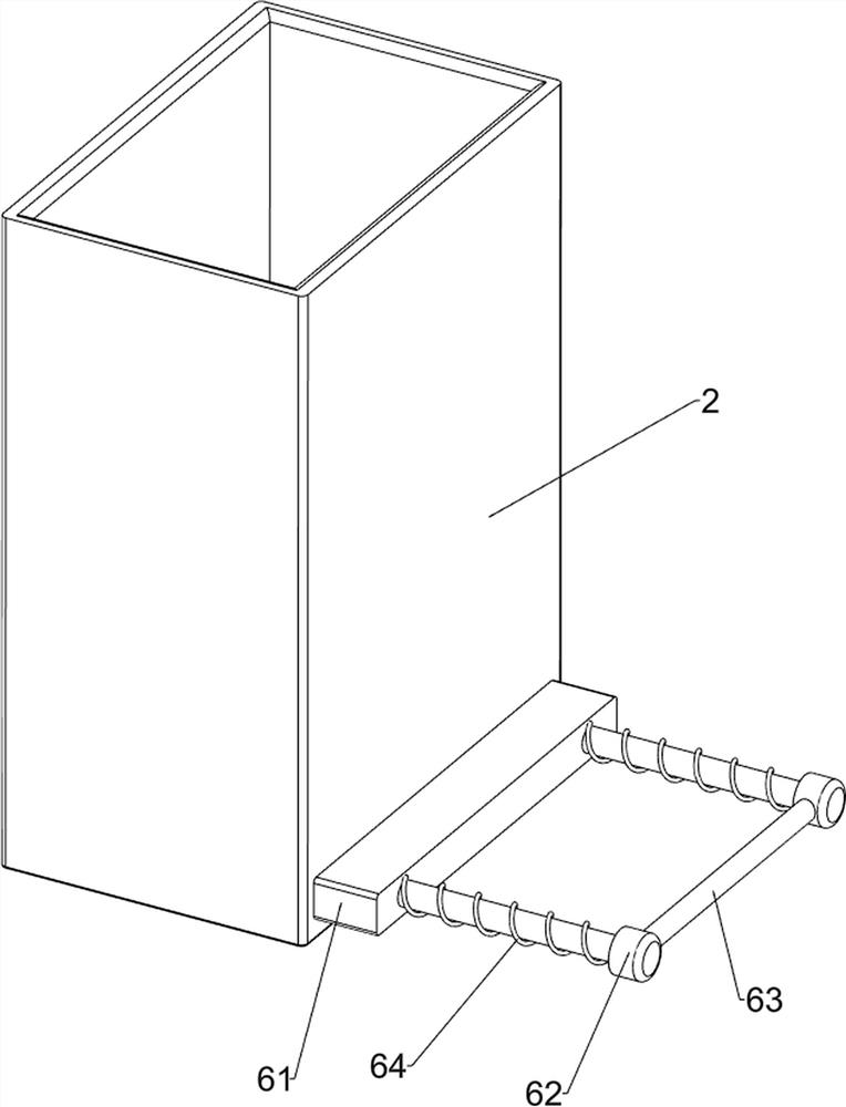
[0087] On the basis of Example 2, such as figure 1 , Figure 5 , Image 6 , Figure 7 and Figure 8 Shown, also comprise drive mechanism 7, push mechanism 8, clamping mechanism 9 and collecting mechanism 10, be provided with drive mechanism 7 on discharge frame 2, piston rod 43 and first connecting rod 63, discharge frame 2 and drive A pushing mechanism 8 is arranged on the mechanism 7 , a clamping mechanism 9 is arranged on the discharging frame 2 and the pushing mechanism 8 , and a collecting mechanism 10 is arranged on the base 1 .

[0088] In the process of bending the sheet metal, the width of the sheet metal is the longest at the beginning, just blocked by the swing rod 53, the clamping mechanism 9 clamps the swing rod 53, and the pushing mechanism 8 clamps the rotating shaft 52, realizing the automatic adjustment of the supporting sheet metal The strength makes the sheet metal more stable when it is bent. After the cylinder 42 is activated, the piston rod 43 moves u...


PUM


Abstract

The invention relates to a bending device, in particular to a stamping and bending device for sheet metal machining. According to the stamping and bending device for sheet metal machining, automatic downward pressing and bending can be achieved, bending is accurate, and operation is safe. The stamping and bending device for sheet metal machining comprises a base, a putting frame, material blocking columns, an extrusion mechanism and a discharging mechanism. The putting frame used for putting is arranged at the upper portion of the base. The material blocking columns used for blocking metal plates are symmetrically arranged at the lower portion of the putting frame; the extrusion mechanism is arranged on the putting frame; and the discharging mechanism is arranged on the putting frame. Through cooperation of the extrusion mechanism and the discharging mechanism, the effect of automatically bending the metal plate is achieved. Through cooperation of the discharging mechanism and a pushing mechanism, people can accurately push the metal plate needing to be bent to the position below an extrusion block to be extruded, errors are reduced, and cost is saved.

Description

technical field [0001] The invention relates to a bending device, in particular to a stamping and bending device for sheet metal processing. Background technique [0002] Sheet metal is a thin metal plate, which is usually plastically deformed by hand or die stamping to obtain the desired shape and size. [0003] The usual method of bending sheet metal is to manually put the metal sheet into the slot, and the pressing device automatically presses down intermittently to bend the material. However, this method needs to manually check the time for placing the material. If the time is not grasped properly , The pressing device is easy to press the worker's hand, causing accidents and inefficiency. [0004] Patent application CN206838828U, with a publication date of 2018.01.05, discloses a welding rod processing and bending device, including a workbench, a first motor, a conveyor belt, a first bending device, a second bending device and a pressure plate. The material is automat...

Claims


Application Information

Patent Timeline
Patent Type & Authority Applications(China)
IPC IPC(8): B21D5/01B21D43/24B21D43/22
CPCB21D5/01B21D43/24B21D43/22
Inventor 龚安国
Owner 龚安国
Why Eureka
Try Eureka