
Low-orbit satellite double-shaft solar wing control and energy balance coupling calculation method

A technology for low-orbit satellites and the sun, which is applied in the overall field of satellites and can solve the problems of reduced power generation efficiency of solar cell arrays, inability to continuously track, and increased included angles.

Active Publication Date: 2021-05-07
航天科工空间工程发展有限公司
View PDF4 Cites 2 Cited by
  • Summary
  • Abstract
  • Description
  • Claims
  • Application Information

AI Technical Summary

Problems solved by technology

Since the attitude of the satellite is greatly affected by the gravity gradient moment, the B axis of the solar wing cannot continuously track the direction of the sun vector, and the angle between the normal direction of the solar wing and the sun vector increases, and the power generation efficiency of the solar array decreases.
At the same time, due to the communication load in the flight direction of the satellite (satellite +X axis, -X axis direction), the solar wing motion envelope needs to avoid the field of view of the communication load antenna, and the solar wing control strategy and energy balance are restricted by various factors. Calculation caused great difficulty

Method used


Image

  • Low-orbit satellite double-shaft solar wing control and energy balance coupling calculation method
  • Low-orbit satellite double-shaft solar wing control and energy balance coupling calculation method
  • Low-orbit satellite double-shaft solar wing control and energy balance coupling calculation method

Examples


no. 1 example

[0053]Table 1 Satellite initial track elements

[0054] Orbital elements Rail height (km) 800 Eccentricity 0.0001 Track tilt, DEG 90 Get off the point of red, DEG 10 Near location angle, DEG 30 Popular point angle, DEG 0 Orbital cycle 100.9min

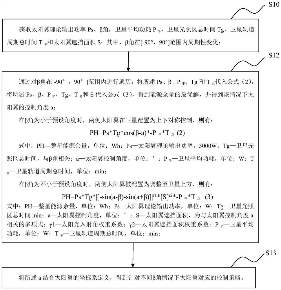
[0055]Such asfigure 1 As shown, one embodiment of the present invention discloses a low-track satellite double-axis solar wing control method, including:

[0056]S10, get the sun wing theory output power PS, β angle, satellite average power consumption Plevel , Satellite Light Zone Total Time Tg, Satellite Rail Cycle Total Time Ttotal And the solar wing occlusion area S; where the β angle is periodically changed in the range of [-90 °, 90 °].

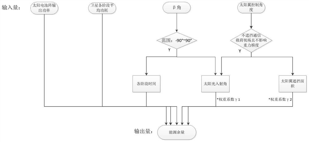
[0057]In a specific embodiment, passimage 3 The satellite energy integrated calculation model is quantitatively calculated, and the solar cell array output power is calculated from the input parameter; according to the full business power consumption of the medium platform and the load, the power consumption ...

no. 2 example

[0085]according toFigure 6 As shown, in 7 years, the interior change indicates that there are a plurality of consecutive growth shadows, and the load time during the playing period is longer, and the discharge depth is large, and the energy balance must be completed in a single-circle. Therefore, the illumination region is except for the full-length load power consumption, it is also necessary to fill the power consumption of the battery storage battery, which can be calculated to have the total current of the solar wing output in the light region. The total current multiplies the output power of the solar battery array by the bus voltage.

[0086]When the satellite is in the illumination area, the solar battery array completes the full stars, the remaining current is charged to the battery, the maximum power consumption of the floor area, and the maximum current is not more than 0.5c when the battery is charged. 40A).

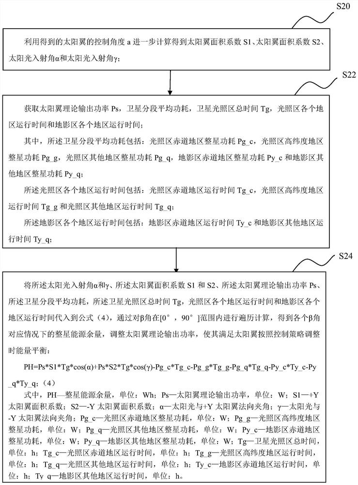
[0087]Such asfigure 2 As shown, one embodiment of the present invent...

no. 3 example

[0122]Figure 9 A computer device is shown in another embodiment of the present application is shown.Figure 9 The displayed computer device 50 is merely an example and should not be restricted to the functions of the present application embodiments. Such asFigure 9 As shown, the computer device 50 is manifested in the form of a general computing device. Component components of computer device 50 may include, but are not limited to, one or more processors or processing unit 500, system memory 516, and bus 501 that connects different system components (including system memory 516 and processing unit 500).

[0123]Bus 501 represents one or more of several types of bus structures, including memory bus, memory controllers, peripheral bus, graphical acceleration port, processor, or a local area bus using any bus structure in a plurality of bus structures. For example, these architecture include, but are not limited to, industrial standard architecture (ISA) bus, microchannel architecture (MAC...


PUM


Abstract

One embodiment of the invention discloses a low-orbit satellite double-shaft solar wing control and energy balance coupling calculation method. The method comprises the steps of obtaining solar wing theoretical output power Ps, a beta angle, satellite average power consumption P (flat), satellite illumination area total time Tg, satellite orbit period total time T sum and solar wing shielding area S, wherein the angle beta periodically changes in a range of [-90 degrees, 90 degrees], traversing the angle beta in the range of [-90 degrees, 90 degrees], calculating to obtain an optimal solution of the energy margin, obtaining a control angle a of the solar wing under the condition, combining the a with a coordinate system definition of the solar wing, and proposing a control strategy corresponding to the solar wing under the condition of different angles beta. The average power consumption of the satellite is calculated in a segmented mode in an orbit period, the on-orbit energy balance condition of the satellite is accurately calculated through a program in combination with an on-orbit control strategy of the solar wing, and an accurate basis is provided for design of the solar wing and a storage battery.

Description

Technical field[0001]The present invention relates to the field of satellite technology. More specifically, there is a low-track satellite biaxial solar wing control method, a energy balance coupling calculation method, a computer device, and a computer readable storage medium.Background technique[0002]Low-rail communication satellites have the characteristics of low orbit height, long traveleration, large communication load power consumption, and strict volumetric weight requirements. The double-axis solar wing has two control axes (A shafts, B shafts), suitable for energy power supply of large orbit tilt satellites, wherein the solar wing a axis around the track surface is a normal direction, and the motor range is 0 ~ 360 °, the sun wing B shaft. Vertical with the A-axis output shaft, the movement range is from 90 ° ~ + 90 °.[0003]Satellite uses two-axis solar wing driving scheme, and the sun wing B shaft when continuous tracking the sun, and under the orbital conditions of the s...

Claims


Application Information

Patent Timeline
Patent Type & Authority Applications(China)
IPC IPC(8): B64G1/10B64G1/44G06F17/15
CPCB64G1/10B64G1/44G06F17/15
Inventor 赵岩杨彪章雷李博贺泉王鑫王进己李月朋
Owner 航天科工空间工程发展有限公司
Learn More