Multi-stage membrane separation equipment

A membrane separation and equipment technology, applied in water/sewage treatment equipment, water/sewage multi-stage treatment, processing wastewater treatment, etc.

Inactive Publication Date: 2021-05-07
广州健创生物技术有限公司
View PDF0 Cites 0 Cited by
  • Summary
  • Abstract
  • Description
  • Claims
  • Application Information

AI Technical Summary

Problems solved by technology

[0002] Membrane separation equipment is a kind of water filtration equipment that separates water and impurities through membranes. It blocks impurities through the difference in diameter between water molecules and other impurities. In the process of sewage treatment in paper mills, sewage contains a large amount of Lignin and cellulose, so the sewage is purified in layers through multi-layer me

Method used


Image

  • Multi-stage membrane separation equipment
  • Multi-stage membrane separation equipment
  • Multi-stage membrane separation equipment

Examples


Embodiment 1

[0024] as attached figure 1 to attach Figure 5 Shown:

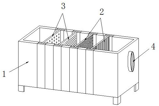
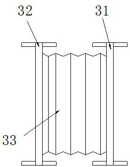
[0025] The present invention provides a multi-layer membrane separation device, the structure of which includes a box body 1, a filter membrane 2, a primary hole 3, and a drainage port 4. The inner side of the box body 1 is movably engaged with the outer side of the filter membrane 2. The outer side of the hole 3 is movably engaged with the inner side of the box body 1, and the drain outlet 4 is embedded and connected with the right end of the box body 1. The primary hole 3 includes a second filter plate 31, a first filter plate 32, and a telescopic plate 33. The outer side of the second filter plate 31 is movably engaged with the inner side of the box body 1 , the right side of the first filter plate 32 is welded to the left side of the telescopic plate 33 , and the right side of the telescopic plate 33 is welded.

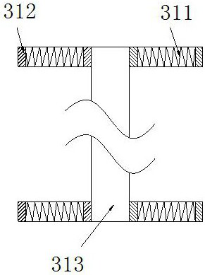
[0026] Wherein, the second filter plate 31 includes a buffer spring 311, a pad 312, and a support block...

Embodiment 2

[0032] as attached Image 6 to attach Figure 7 Shown:

[0033] Wherein, the telescopic plate 33 includes an impact plate 331, a folded layer 332, and a reset rod 333. The outer side of the impact plate 331 is welded to the outer side of the second filter plate 31, and the folded layer 332 is bolted to the outer side of the impact plate 331. The reset rod 333 is embedded and connected to the inner side of the impact plate 331. The material of the reset rod 333 is carbon spring steel, which has the characteristics of high elasticity and fatigue resistance, so that the impact plate 331 is impacted and compressed by the second filter plate 31. It can be automatically restored, and the frequency of cleaning the flocs has been improved, as stated.

[0034] Wherein, the impact plate 331 includes a fixed frame 31a, an oblique opening 31a, and a storage cavity 31c, the outer side of the fixed frame 31a is embedded and connected with the outer side of the reset rod 333, and the obliq...


PUM


Abstract

The invention discloses multi-stage membrane separation equipment which structurally comprises a box body, a filter membrane, a first-stage hole and a water outlet, the inner side of the box body is movably clamped with the outer side of the filter membrane, the outer side of the first-stage hole is movably clamped with the inner side of the box body, and the water outlet is fixedly connected with the right end of the box body in an embedded mode. In the shaking process of a supporting block, flowing of water flow drives a blocking plate to rotate in a filtering frame through a connecting shaft to capture floccules, a buffer plate swings to a certain degree to increase the blocking area of a plate body in the capturing process, then the floccules are hooked through a hook head, the floccules are prevented from flowing to the filter membrane and the blocking effect is improved, and the filtering stage efficiency is improved. After the impact plate is impacted, a large amount of water contained in the storage cavity can be sprayed out towards the two sides when passing through the inclined opening, floccules originally flowing along the water flow are disturbed and prevented from directly flowing away from the holes, the blocking amount of the blocking plate is reduced, the service life of the blocking plate is prolonged, the contact area of the filter membrane and sewage is increased, and the filtering capacity is improved.

Description

technical field [0001] The invention belongs to the field of membrane separation equipment, and more specifically, relates to a multi-layer membrane separation equipment. Background technique [0002] Membrane separation equipment is a kind of water filtration equipment that separates water and impurities through membranes. It blocks impurities through the difference in diameter between water molecules and other impurities. In the process of sewage treatment in paper mills, sewage contains a large amount of Lignin and cellulose, so the sewage is purified in layers through multi-layer membrane separation equipment. During the purification process of sewage, flocculants will be added to gather fine fibers in the water, but because part of the flocs will pass along the direction of water flow The initial filter holes cause the surface of the subsequent filter membrane to be blocked by too much floc, which reduces the water flow of the filter holes and increases the filtration t...

Claims


Application Information

Patent Timeline
IPC IPC(8): C02F9/04C02F103/28
CPCC02F1/001C02F1/44C02F1/52C02F9/00C02F2103/28C02F2201/002C02F2201/004C02F2303/14C02F2303/16
Inventor 刘贻刁
Owner 广州健创生物技术有限公司
Why Eureka
Try Eureka