
Spray turbulence device for air flow in internal combustion engine cylinder

A technology of spoiler and internal combustion engine, which is applied to internal combustion piston engines, valve devices, combustion engines, etc., can solve the problems of uneven ignition, achieve the effects of improving combustibility, ensuring diffusivity, and improving the effect of atomization impact

Active Publication Date: 2021-05-07
浙江方圆检测集团股份有限公司
View PDF6 Cites 0 Cited by
  • Summary
  • Abstract
  • Description
  • Claims
  • Application Information

AI Technical Summary

Problems solved by technology

[0003] In the current internal combustion engine, before the oil mist enters the piston for ignition, the oil mist diffuses irregularly, so after ignition, there will be uneven ignition

Method used


Image

  • Spray turbulence device for air flow in internal combustion engine cylinder
  • Spray turbulence device for air flow in internal combustion engine cylinder
  • Spray turbulence device for air flow in internal combustion engine cylinder

Examples


Embodiment 1

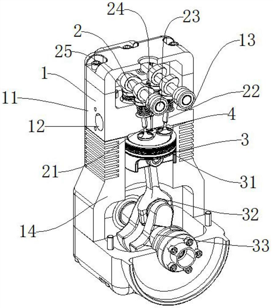
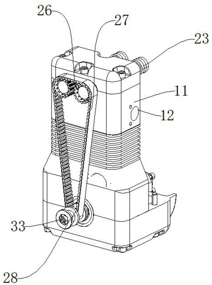
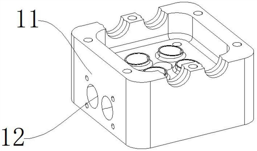
[0034] Such as Figure 1-Figure 5 As shown, an internal combustion engine in-cylinder airflow spray disturbance device includes a housing mechanism 1, an ignition mechanism 2, a crank linkage mechanism 3, and a spray disturbance mechanism 4. The housing mechanism 1 is internally provided with an ignition mechanism 2, and the ignition mechanism 2 A crank linkage mechanism 3 is arranged on the lower side, and a spray spoiler mechanism 4 is arranged between the ignition mechanism 2 and the crank linkage mechanism 3;

[0035] The housing mechanism 1 includes an ignition stable housing 11, an air inlet 12, an air outlet 13, and an oil pan 14. One end of the ignition stable housing 11 is formed with an air inlet 12, and the other end of the ignition stable housing 11 is formed with an air outlet 13. , the lower end of the ignition stabilization housing 11 is connected to the oil pan 14;

[0036] Ignition mechanism 2 comprises intake valve 21, exhaust valve 22, camshaft 23, spark pl...


PUM


Abstract

The invention discloses a spray turbulence device for air flow in an internal combustion engine cylinder. The device comprises a shell mechanism, an ignition mechanism, a crank-link mechanism and a spray turbulence mechanism. The ignition mechanism is arranged in the shell mechanism, and the crank-link mechanism is arranged on the lower side of the ignition mechanism. And the spray turbulence mechanism is arranged between the ignition mechanism and the crank-link mechanism. According to the spray turbulence device, lateral low-pressure and forward high-pressure airflow can be formed through an acceleration valve and a conical acceleration block, so that oil mist is accelerated, the oil injection effect is improved, the turbulent flow effect is improved through the spiral structure of a turbulent flow groove, the atomization impact effect can be improved through the situation that a lower opening is large, the diffusivity of the oil mist is guaranteed, and the combustibility is improved.

Description

technical field [0001] The invention relates to the field of internal combustion engines, in particular to a spray turbulence device for airflow in a cylinder of an internal combustion engine. Background technique [0002] An internal combustion engine is a kind of power machinery, which is a heat engine that directly converts the heat energy released by burning fuel inside the machine into power. Internal combustion engines in a broad sense include not only reciprocating piston internal combustion engines, rotary piston engines and free piston engines, but also rotary impeller jet engines, but the internal combustion engines generally refer to piston internal combustion engines. Piston type internal combustion engine is the most common with reciprocating piston type. The piston-type internal combustion engine mixes fuel and air and burns it in its cylinder, and the heat energy released makes the cylinder generate high-temperature and high-pressure gas. The expansion of th...

Claims


Application Information

Patent Timeline
Patent Type & Authority Applications(China)
IPC IPC(8): F01L3/06F01L3/24F01L1/46
CPCF01L3/06F01L3/24F01L1/46Y02T10/12
Inventor 翁文祥李伟权陈锋程力黄顺民岳高东
Owner 浙江方圆检测集团股份有限公司
Learn More