Maneuvering array orientation estimation method based on sparse Bayesian learning

A sparse Bayesian and azimuth estimation technology, applied in the field of maneuvering array azimuth estimation based on sparse Bayesian learning, can solve problems such as unsatisfactory performance, improve the accuracy of azimuth estimation and azimuth resolution, and solve the ambiguity of starboard and starboard , Suppress the effect of port and starboard blur

Pending Publication Date: 2021-05-07
HARBIN ENG UNIV
View PDF5 Cites 4 Cited by
  • Summary
  • Abstract
  • Description
  • Claims
  • Application Information

AI Technical Summary

Problems solved by technology

However, the performance of such methods is not ideal under the condition of low signal-to-noise ratio and small number of snapshots

Method used


Image

  • Maneuvering array orientation estimation method based on sparse Bayesian learning
  • Maneuvering array orientation estimation method based on sparse Bayesian learning
  • Maneuvering array orientation estimation method based on sparse Bayesian learning

Examples


specific Embodiment 1

[0065]according toFigure 1 - Figure 6As shown, the present invention provides a method of maneuvering an array based on sparse Bayes, including the following steps:

[0066]Motor array azimuth estimation method based on sparsebieles learning, including the following steps:

[0067]Step 1: Construct a sparse signal model of a motor array according to the array of sonar arrays and platform navigation systems.

[0068]The step 1 is specifically:

[0069]Step 1.1: Set k in the direction of the land coordinate system θ = {θ1, ..., θK} Of the far field narrowband signal, where θKFor the kth far field narrowband signal, it is incident on a uniform linear array of half-wavelength composed of M element and the group pitch, and the incident direction remains unchanged within the observation time, when the array occurs, the array pointing It will change over time, indicating the guide vector of the target signal by the following formula.t(k):

[0070]

[0071]

[0072]Among them, λ is the signal wavelength,Timing ...

specific Embodiment 2

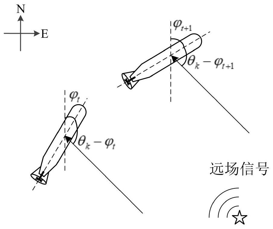
[0118]Schematic diagrams of the actuation of the remote field goals such asfigure 1 Indicated. Assume that K is θ = {θ in the direction of the earth coordinate system1, ..., θK} The far field narrowband signal is incorporatedized from the M group elements, and the spacing of the group element is on the uniform linear array of the half-wavelength, and the incident direction remains unchanged within the observation time. When the array occurs, the pointing point of the array will change over time, the guide vector of the target signal can be expressed as

[0119]

[0120]among them,(·)TIndicates the matrix transposition, λ is the signal wavelength,Timed the angular angle of the time change, T indicate the moment. As shown in the formula (1), the orientation vector At(k) Not only with the azimuth θ of the target under the land coordinateskRelated to arrays that are also related to the timerelated. Therefore, the array receive signal model can be expressed as

[0121]X (t) = at(θ) s (t) + n (t),...


PUM


Abstract

The invention relates to a maneuvering array orientation estimation method based on sparse Bayesian learning. The invention relates to the technical field of sonar detection, and the method comprises the steps of constructing a maneuvering array sparse signal model according to a sonar array shape and an array directional angle provided by a platform navigation system; based on Gaussian distribution hypothesis of received noise, establishing a maneuvering array sparse Bayesian learning framework, and determining a posterior distribution form of array received signals; and performing logarithm maximization operation according to the posterior distribution form of the array receiving signals to obtain a far-field target orientation. According to the invention, the maneuvering array orientation estimation problem is solved by using the thought of sparse Bayesian learning, the orientation estimation precision and the orientation resolution capability are effectively improved, and meanwhile, the ambiguity of the port and the starboard can be more effectively inhibited.

Description

Technical field[0001]The present invention relates to the field of sonar detection techniques, and is a maneuvering array orientation estimation method based on sparsebased.Background technique[0002]A position for far field goals is one of the important tasks of passive nna. In recent years, the sonar array has been widely installed on mobile platforms such as unin-underwater steam. With the mobile platform, the left-right direction of the left-right direction in the right side of the linear sonar array can be effectively solved. When the platform is mobile, the movement of the sonar array can be decomposed into translational motion and array pointing changes. The panning motion distance of the array can be ignored compared to the distance between the far field goals and the platform. Array points change cause the time change of the target orientation information in the pick-up, and thus cannot be ignored. For many traditional orientation estimation methods, such as minimum variance...

Claims


Application Information

Patent Timeline
Patent Type & Authority Applications(China)
IPC IPC(8): G06K9/62G06F17/16G01S15/88
CPCG06F17/16G01S15/88G06F18/29
Inventor 郝宇邱龙皓王燕赵磊付进邹男齐滨王晋晋王逸林张光普梁国龙
Owner HARBIN ENG UNIV
Why Eureka
Try Eureka