One-plate three-field ultrathin fuel cell bipolar plate and fuel cell stack

A fuel cell stack and fuel cell technology, applied in fuel cells, fuel cell parts, circuits, etc., can solve the problem of vibration resistance, bending resistance and air tightness, sacrificial electrical conductivity, thermal conductivity, flow field plate combination Difficult problems, to achieve the effect of improving heat dissipation, shortening the path of heat transfer, and increasing the volume ratio power density

Pending Publication Date: 2021-05-07
TONGJI UNIV
View PDF5 Cites 4 Cited by
  • Summary
  • Abstract
  • Description
  • Claims
  • Application Information

AI Technical Summary

Problems solved by technology

However, due to the demand for mechanical strength, reducing the thickness of the bipolar plate through the application of non-metallic materials will affect its anti-vibration, bending resistance and air tightness, and even sacrifice electrical conductivity and thermal conductivity, which is not worth the candle.
In addition, the function of the flow field is to transmit the anion and cation reagents and cooling water to meet the fluid requirements for normal power generation, especially for high current power generation. The groove depth of the fluid should not be too shallow, which also limits the further expansion Thinning
[0011] CN112164810 discloses a fuel cell ultra-thin bipolar plate and a fuel cell stack, the fuel gas flow path includes at least two grooves with different groove depths, the oxidizing gas flow path includes at least one groove depth, the anode plate and the cathode When t

Method used


Image

  • One-plate three-field ultrathin fuel cell bipolar plate and fuel cell stack
  • One-plate three-field ultrathin fuel cell bipolar plate and fuel cell stack
  • One-plate three-field ultrathin fuel cell bipolar plate and fuel cell stack

Examples


Embodiment

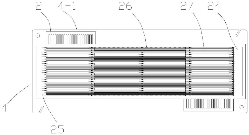
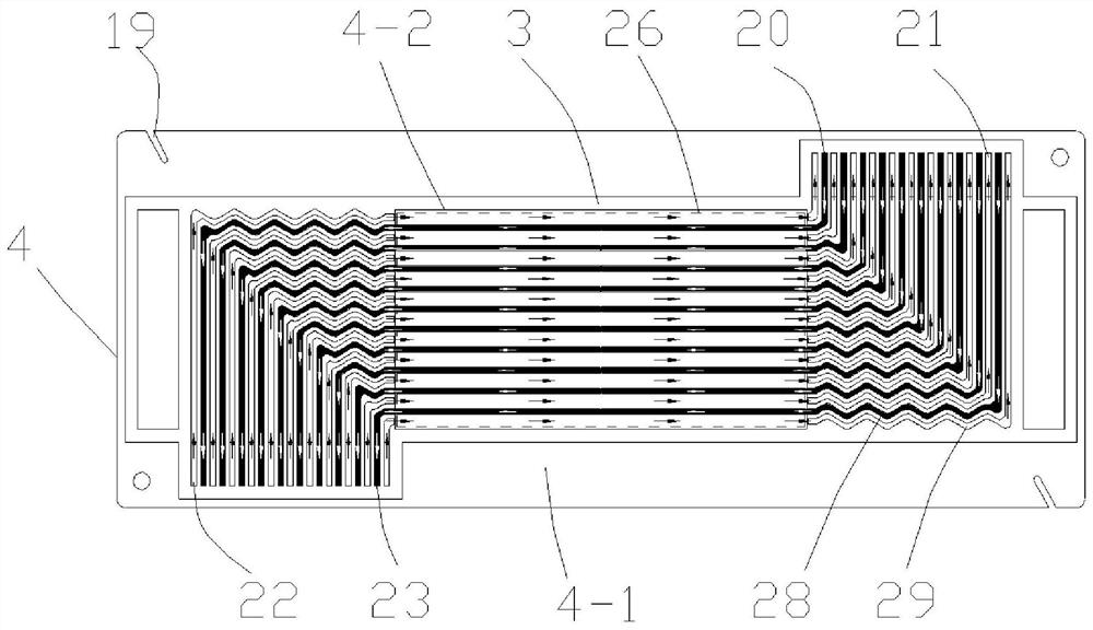
[0066] A one-plate three-field type ultra-thin fuel cell bipolar plate, the bipolar plate 4 includes a flow field plate 4-1, one side of the flow field plate 4-1 is an anode side, and the other side is a cathode side;

[0067] A fuel gas flow channel 28 and a cooling liquid flow channel 29 are arranged on the anode side of the flow field plate 4-1;

[0068] An oxidizing gas flow channel 27 is arranged on the cathode side of the flow field plate 4-1;

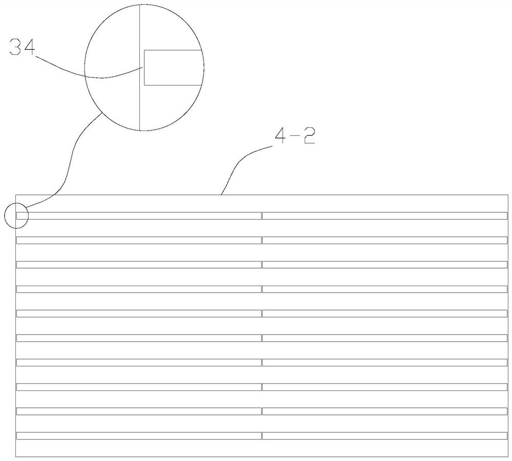
[0069] The bipolar plate 4 also includes a cover plate 4-2 placed on the anode side of the flow field plate 4-1 for separating the coolant flow channel 29 located in the active area from the fuel gas flow channel 28;

[0070] The anode side of the flow field plate 4-1 is used to closely cooperate with the anode seal 3 and the cover plate 4-2 to form a fuel gas flow field and a coolant flow field;

[0071] The cathode side of the flow field plate 4 - 1 is used to closely cooperate with the cathode seal 2 to form an oxidizing gas ...


PUM


Abstract

The invention relates to a one-plate three-field ultrathin fuel cell bipolar plate and a fuel cell stack. The bipolar plate comprises a flow field plate, one side of the flow field plate is an anode side, and the other side of the flow field plate is a cathode side; a fuel gas flow channel and a cooling liquid flow channel are arranged on the anode side of the flow field plate; an oxidizing gas flow channel is arranged on the cathode side of the flow field plate; the bipolar plate further comprises a cover plate which is arranged on the anode side of the flow field plate and used for separating the cooling liquid flow channel and the fuel gas flow channel located in the active area; the anode side of the flow field plate is used for being tightly matched with an anode sealing piece and the cover plate to form a fuel gas flow field and a cooling liquid flow field; and the cathode side of the flow field plate is used for being tightly matched with a cathode sealing piece to form an oxidizing gas flow field. The three flow fields are concentrated on one plate, so that the thickness of the bipolar plate can be greatly reduced, the volume of a galvanic pile is greatly reduced, and the volumetric specific power density of the galvanic pile is improved.

Description

technical field [0001] The invention belongs to the technical field of fuel cells, in particular to a one-plate three-field ultra-thin fuel cell bipolar plate and a fuel cell stack. Background technique [0002] Proton exchange membrane fuel cell (PEMFC) uses clean energy hydrogen as fuel, has the characteristics of high conversion efficiency and non-polluting reaction products, and is an ideal new energy carrier for transportation. However, due to certain technical bottlenecks in the current fuel cell (such as insufficient power density, insufficient life, etc.), the cost of using the fuel cell stack remains high. In the early stage of the commercialization of fuel cell vehicles, fuel cell heavy trucks, container logistics vehicles, locomotives, and ships that can achieve fixed-point refueling and are suitable for long-distance transportation are increasingly valued; The design, development and fabrication of efficient fuel cell stacks presents an urgent need. [0003] At...

Claims


Application Information

Patent Timeline
IPC IPC(8): H01M8/026H01M8/0263H01M8/0267H01M8/2457
CPCH01M8/026H01M8/0263H01M8/0267H01M8/2457Y02E60/50
Inventor 明平文杨代军李冰张存满
Owner TONGJI UNIV
Why Eureka
Try Eureka