
Novel combustion box of wood particle furnace

A technology of burning box and wood pellets, which can be used in household stoves/stoves, solid heating fuels, climate sustainability, etc., and can solve problems such as waste of fuel, excessive smoke and dust, pollution, etc.

Pending Publication Date: 2021-05-11
JINHUA XINAN ELECTRICAL CO LTD
View PDF0 Cites 1 Cited by
  • Summary
  • Abstract
  • Description
  • Claims
  • Application Information

AI Technical Summary

Problems solved by technology

[0003] However, the combustion box, the core component of a traditional wood pellet stove, is basically a single-wall barrel-shaped cylinder with an open top, and wood pellets and air are mixed and burned at the bottom of the cylinder. Since only a single incomplete combustion can be achieved, more Smoke and dust not only cause pollution but also waste fuel, which is not conducive to the environmental protection goals of cleaning, energy saving and emission reduction

Method used


Image

  • Novel combustion box of wood particle furnace
  • Novel combustion box of wood particle furnace
  • Novel combustion box of wood particle furnace

Examples


Embodiment 1

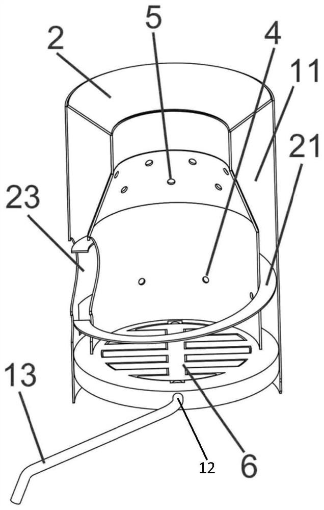
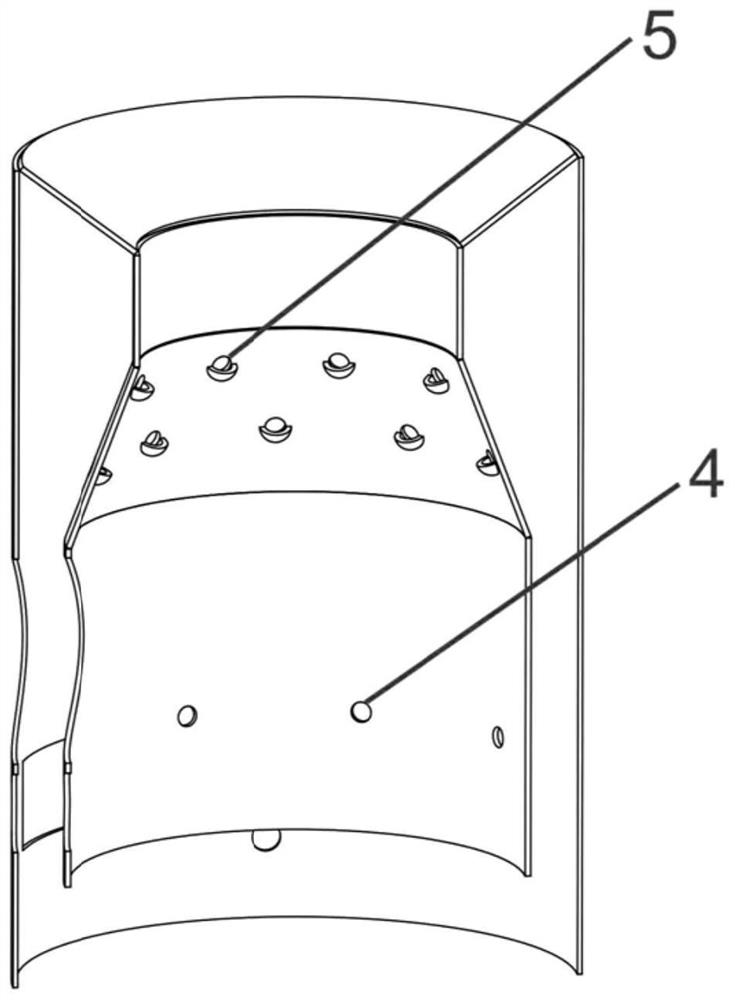
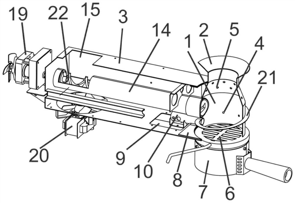
[0029] A combustion box 1 comprises a combustion box wall 2 and a combustion box bottom plate 6 installed at the bottom of the combustion box, the combustion box wall has a hollow interlayer air duct 11 (the combustion box wall is a double-layer structure, and the two ends of the combustion box wall The part is closed and hollow in the middle, and the interlayer of the hollow part is used as air flow), and the bottom and top of the inner wall of the combustion box are respectively provided with a bottom air inlet 4 and a top air inlet 5 that communicate with the interlayer air duct 11, such as figure 1 shown. From figure 1 It can be seen that the combustion box bottom plate 6 is installed on the bottom of the combustion box, and the bottom air inlet hole 4 is located above the combustion box bottom plate 6 . The combustion box outer wall can be provided with the air supply port 23 that communicates with the interlayer air duct 11 according to common knowledge, and the air sup...

Embodiment 2

[0037] Embodiment 2 is substantially the same as Embodiment 1, except that the rotating shaft 12 can be rotated by a motor 16 instead of manual rotation. The free end of the rotating shaft 12 is connected with the servo motor 16. After the movable part of the combustion box bottom plate is electrically driven to rotate 90 degrees by the servo motor 16 through the rotating shaft 12 to become vertical, the slag on the combustion box bottom plate can be smoothly poured under the action of gravity. Put it into the ash box 7 at the bottom of the combustion box, and then the bottom plate will return to the normal horizontal state. Afterwards, the ash box can be taken out to remove the slag and then put it back to the bottom of the combustion box, which saves the need to disassemble the top of the combustion box when cleaning the traditional ash. It takes time and effort to remove the fire cover and drip pan and clean it from above.


PUM


Abstract

The invention discloses a novel combustion box of a wood particle furnace. The novel combustion box comprises a combustion box wall and a combustion box bottom plate, the combustion box wall is provided with a hollow interlayer air duct, an air supply outlet communicating with the interlayer air duct is formed in the outer wall of a combustion box body, and a bottom air inlet hole and a top air inlet hole which communicate with the interlayer air duct are respectively formed in the bottom and the top of the inner wall of the combustion box body. The combustion box wall is arranged to be of the hollow interlayer structure, so that a part of air entering the interlayer air duct can enter from the bottom air inlet hole to be mixed with ignited wood particles for primary combustion; and the other part of air is blown out from the top air inlet hole after being preheated by the interlayer air duct, and is mixed with hot flue gas and dust after primary combustion for secondary combustion. Two times of combustion can raise the roasting temperature in a furnace chamber to more than 800 Fahrenheit degree, on the other hand, flue gas and dust are burnt as much as possible, the cleanliness in a hearth is greatly improved, the combustion efficiency and the fuel utilization rate are improved, and the energy-saving and environment-friendly advantages of the wood particle furnace are highlighted.

Description

technical field [0001] The application belongs to the technical field of combustion boxes for wood pellet stoves (including food ovens and heating stoves), and in particular relates to a novel combustion box for wood pellet stoves. Background technique [0002] With the increasing use of wood pellet stoves (including food ovens and heating stoves) on the market, people are increasingly pursuing thermal efficiency during use, high environmental cleanliness, and the convenience of cleaning residues after combustion. [0003] However, the combustion box, the core component of a traditional wood pellet stove, is basically a single-wall barrel-shaped cylinder with an open top, and wood pellets and air are mixed and burned at the bottom of the cylinder. Since only a single incomplete combustion can be achieved, more Smoke and dust not only cause pollution but also waste fuel, which is not conducive to the environmental protection goals of cleaning, energy saving and emission reduc...

Claims


Application Information

Patent Timeline
IPC IPC(8): F24B1/197F24B1/19F24B1/189F24B1/191F24B13/04F24B13/00
CPCF24B1/197F24B1/19F24B1/189F24B1/191F24B13/04F24B13/006Y02B40/00
Inventor 宋秉禄
Owner JINHUA XINAN ELECTRICAL CO LTD
Learn More