Petrochemical engineering heating furnace
A petrochemical and heating furnace technology, applied in the field of heating furnaces and petrochemical heating furnaces, can solve problems such as heat loss and achieve the effect of avoiding loss and waste
- Summary
- Abstract
- Description
- Claims
- Application Information
AI Technical Summary
Problems solved by technology
Method used
Image

Examples
Embodiment 1
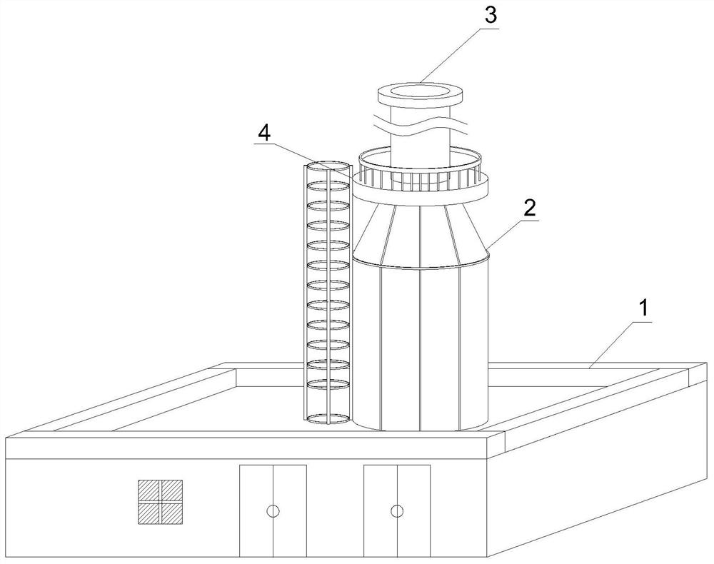
[0034] Such as Figure 1-9 As shown, the present invention provides a petrochemical heating furnace, comprising a plant mechanism 1 and a ladder 4, the middle part of the upper end of the plant mechanism 1 is fixedly connected with a heating furnace body 2, and the upper end of the heating furnace body 2 is fixedly connected with a discharge hole 3. One side of the furnace body 2 is provided with a ladder 4, the heating furnace body 2, the discharge hole 3 and the ladder 4 are all arranged above the plant mechanism 1, the heating furnace body 2 includes a No. A No. 1 cold water inlet pipe 252 is movably connected to the upper end, and the discharge hole 3 includes a No. 1 harmful impurity removing block 331 , and a No. 2 harmful impurity removing block 333 is arranged on one side of the No. 1 harmful impurity removing block 331 .
[0035] In this embodiment, No. 1 harmful impurity removal block 331 is provided with activated carbon material inside, which can simply absorb the ...
Embodiment 2
[0037] Such as Figure 1-9 Shown, on the basis of embodiment 1, the present invention provides a kind of technical scheme:
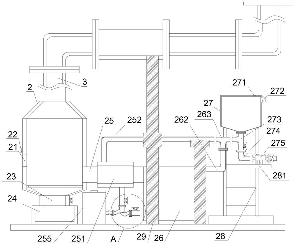
[0038] Preferably, one side of the heating furnace body 2 is provided with a feed inlet 21, and one side of the heating furnace body 2 is movably connected with a feed inlet door 22, and the lower end of the heating furnace body 2 is fixedly connected with a residue outlet 23, and the bottom of the residue outlet 23 The lower end is provided with a No. 1 material storage box 24, and the other side of the heating furnace body 2 is fixedly connected with a discharge pipe 25, and one end of the discharge pipe 25 is movably connected with a No. 2 material storage box 26, and one side of the No. 2 material storage box 26 A fixed support frame 28 is provided, the upper end of the fixed support frame 28 is fixedly connected with a cooling water tank 27, the lower end of the No. 1 cold water inlet pipe 252 is movably connected with a support frame 29, and the lo...
Embodiment 3
[0040] Such as Figure 1-9 Shown, on the basis of embodiment 1, the present invention provides a kind of technical scheme:
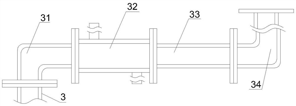
[0041] Preferably, the upper end of the discharge hole 3 is movably connected with a No. 4 connector 31, and one end of the No. 4 connector 31 is movably connected with a No. 2 heat absorption pipe 32, and one end of the No. 2 heat absorption pipe 32 is movably connected with a purification connecting pipe 33. One end of the purification connection pipe 33 is movably connected with a purification exhaust pipe 34, and both sides of the No. 1 harmful impurity removal block 331 are provided with fixed nets 332, and the No. 1 harmful impurity removal block 331, the fixed net 332 and the No. 333 are all arranged inside the purification connecting pipe 33. The present invention effectively cools the directly discharged high-temperature harmful gas through the setting of the No. 2 heat absorption pipe 32. After cooling down, the gas passes through the purificat...
PUM
 Abstract
Description
Claims
Application Information
 - R&D
- Intellectual Property
- Life Sciences
- Materials
- Tech Scout
- Unparalleled Data Quality
- Higher Quality Content
- 60% Fewer Hallucinations
Browse by: Latest US Patents, China's latest patents, Technical Efficacy Thesaurus, Application Domain, Technology Topic, Popular Technical Reports.
© 2025 PatSnap. All rights reserved.Legal|Privacy policy|Modern Slavery Act Transparency Statement|Sitemap|About US| Contact US: help@patsnap.com