Rotor engine air passage steady flow test device

A rotary engine and test device technology, which is applied in the direction of internal combustion engine testing, etc., can solve the problems of no valve mechanism and impossibility to measure the performance of the airway of the rotary engine.

Pending Publication Date: 2021-05-11
CHINA NORTH ENGINE INST TIANJIN
View PDF9 Cites 0 Cited by
  • Summary
  • Abstract
  • Description
  • Claims
  • Application Information

AI Technical Summary

Problems solved by technology

[0005] However, because the intake and exhaust ports are arranged at fixed positions on the body and there is no valve train, the conventional airway steady flow test cannot measure the airway performance of the rotary engine

Method used


Image

  • Rotor engine air passage steady flow test device
  • Rotor engine air passage steady flow test device
  • Rotor engine air passage steady flow test device

Examples


Embodiment Construction

[0026]It should be noted that the features in the present invention in the present invention can be combined with each other in the case of an unable conflict.

[0027]In the description of the present invention, it is to be understood that the terms "center", "longitudinal", "horizontal", "upper", "lower", "front", "post", "left", "right", " The orientation of the orientation of the orientation of the direction "," horizontal "," top "," bottom "," inside "," outside ", etc. is based on the orientation or positional relationship shown in the drawings, is only for convenience of describing the present invention and Simplify the description, rather than indicating or implying that the device or element must have a specific orientation, constructed and operated in a particular direction, and thus is not to be construed as limiting the invention. Moreover, the terms "first", "second", etc. are only used to describe purposes, and cannot be understood as an indication or implies relative im...


PUM


Abstract

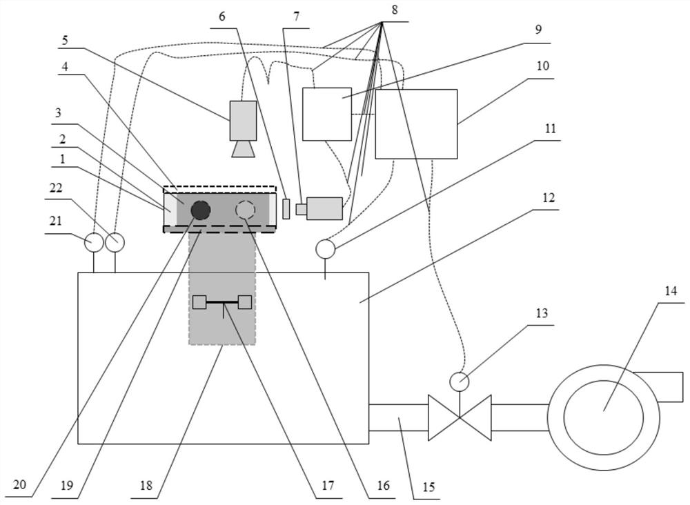
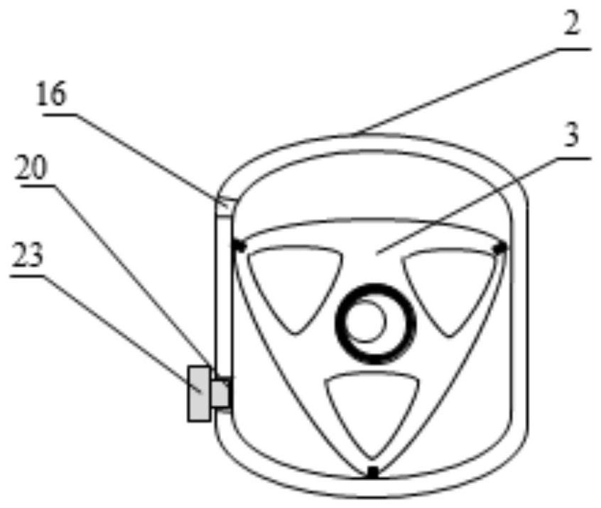
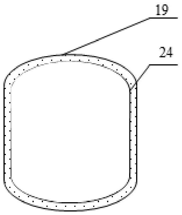
The invention provides a rotor engine air passage steady flow test device. The rotor engine air passage steady flow test device comprises a rotor engine test piece, a wire harness, a CCD camera, a synchronizer, a controller, a pressure stabilizing box pressure sensor, a pressure stabilizing box, a gas flowmeter, a fan, a pipeline, a blade anemograph, a simulation cylinder sleeve, an atmospheric pressure sensor and an atmospheric temperature sensor. Based on the principle of an air passage steady flow test, stable pressure difference is generated through a fan, pressure and temperature at two ends of an air inlet of the rotor engine are measured, theoretical flow is obtained through a Bernoulli equation, actual gas flow is obtained through a gas flow meter in front of the fan, vortex is measured through a blade anemograph, the flow coefficient and the swirl ratio of the air inlet can be accurately calculated, the flow capacity of the air inlet of the rotor engine can be evaluated, the internal flow field of the rotor engine test piece is measured through the CCD camera, the capacity of the air inlet for generating in-cylinder flow is evaluated, and the design of the air inlet is guided.

Description

Technical field[0001]The present invention relates to the field of internal combustion engines, in particular, to a rotor engine airway stabilization test device.Background technique[0002]In modern internal combustion engines, air flow has a very important status. It is one of the three elements in the combustion process of the internal combustion engine, and the quality of various internal combustion engine combustion processes are different degrees, even to a large extent to the state of air, oil and gas and gas.[0003]The airflow motion in the cylinder in the intake process is very complicated. It does not only change as the crankshaft corner and the gas phase, but also along the position along the cylinder radial and axial direction; and it continues to change the flow rate and the direction of motion, the rotation center and the flow state are constantly changing.[0004]The rotor engine utilizes the rotor rotation to do work, directly output power, and removes dozens of moving pa...

Claims


Application Information

Patent Timeline
IPC IPC(8): G01M15/05
CPCG01M15/05
Inventor 王子玉李耀宗程秀围王占广李研芳车凯凯朱伟青文明刘金龙曹如楼李超凡李玉峰
Owner CHINA NORTH ENGINE INST TIANJIN
Why Eureka
Try Eureka