Sleeve rotating device

A technology of rotating device and bushing, applied in switchgear, fully enclosed busbar device, busbar installation, etc., can solve the problem of high bushing, and achieve the effect of reducing height, convenient installation and simple structure

Active Publication Date: 2021-05-11
STATE GRID CORP OF CHINA +1
View PDF6 Cites 6 Cited by
  • Summary
  • Abstract
  • Description
  • Claims
  • Application Information

AI Technical Summary

Problems solved by technology

[0004] The purpose of the present invention is to provide a bushing rotating device to solve the technical problem that the bushing of the switch product in the prior art is high and the switch product needs to be disassembled

Method used


Image

  • Sleeve rotating device
  • Sleeve rotating device
  • Sleeve rotating device

Examples


Embodiment 1

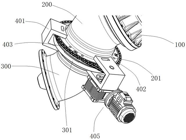
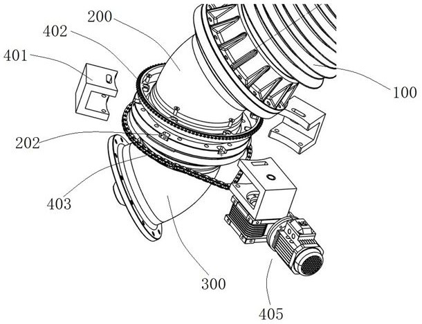
[0043] Such as Figure 1 to Figure 6 As shown, the bushing rotating device is used to drive the bushing cylinder 200 to rotate around the central axis of the bushing cylinder flange 201 and the busbar cylinder flange 301, lower the bushing, and reduce the overall height of the high-voltage switch to facilitate transportation , during on-site installation, reversely rotate the bushing cylinder 200 to erect the bushing upwards again.

[0044] The casing rotation device includes two parts, one part is the limit part, which ensures that the casing cylinder 200 and the casing 100 will not fall during the rotation of the casing; the other part is the driving part, which is used to control the casing cylinder 200 Apply torque to cause rotation.

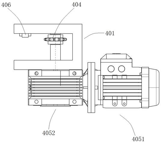
[0045] The limiting part of the present embodiment includes three U-shaped limiting blocks 401, and the structure of the U-shaped limiting blocks 401 is as follows: Figure 5 As shown, the U-shaped limiting block 401 includes an installati...

specific Embodiment 2

[0061] In Embodiment 1, there are protrusions on the split lobes of the sprocket and grooves on the flange of the sleeve cylinder, so that the first sprocket can be integrally fitted outside the flange of the sleeve cylinder. In this embodiment, the sprocket split flap is fixedly installed on one side of the flange of the sleeve body. At this time, the limit side wall of the U-shaped limit block needs to cooperate with the sprocket split flap to prevent the casing barrel from The body and casing are dumped.

specific Embodiment 3

[0063] In Embodiment 1, the first sprocket is fixedly installed on the flange of the sleeve cylinder, and then installed on the sleeve cylinder. In this embodiment, the first sprocket can be fixedly installed on the part of the sleeve cylinder except the flange of the sleeve cylinder. Specifically, each sprocket of the first sprocket is buckled on the sleeve sleeve On the body, bolts and nuts are used to fix each sprocket sub-lobes to each other, and they are tightly fixed on the sleeve barrel by means of clamping.


PUM


Abstract

The invention relates to a sleeve rotating device which comprises a limiting part, the limiting part comprises at least three U-shaped limiting blocks, each U-shaped limiting block is provided with a bus barrel mounting part used for being mounted on a bus barrel, each U-shaped limiting block comprises a limiting side wall. The limiting side wall is used for being in stopping fit with the sleeve barrel flange in the axial direction of the sleeve barrel flange; the sleeve rotating device further comprises a driving part, the driving part comprises a chain wheel and chain mechanism, and the chain wheel and chain mechanism comprises a first chain wheel, a second chain wheel and a chain wound around the two chain wheels. The first chain wheel is arranged outside a sleeve cylinder in a sleeving mode when used, the first chain wheel comprises at least two chain wheel sections which are arranged in a split mode, and the chain wheel sections are oppositely combined to form the first chain wheel. The driving part further comprises a power unit, the power unit is fixedly arranged on one U-shaped limiting block, and the second chain wheel is in transmission connection with the power unit so as to rotate around the axis of the second chain wheel.

Description

technical field [0001] The invention relates to a casing rotating device. Background technique [0002] Switching appliances have certain restrictions on the transportation height. If the product is too high and exceeds the transportation height, the product needs to be transported separately, and then the on-site docking will be carried out on the project site. For high-voltage switches, on-site docking not only means that the workload is doubled, but after the docking is completed, the gas chamber needs to be processed, and the withstand voltage test needs to be re-conducted to ensure the reliability of the assembly. The quality risk and cost are greatly increased. Increase. The super high part of the switch product is mostly the inlet and outlet bushing. The layout of the bushing is shown in the Chinese utility model patent with the authorized announcement number CN204615167U. The bushing is installed on the busbar barrel through the bushing barrel. The busbar barrel inc...

Claims


Application Information

Patent Timeline
Patent Type & Authority Applications(China)
IPC IPC(8): H02G5/06H02B3/00
CPCH02G5/061H02B3/00
Inventor 徐仲勋谭盛武郝留成魏建巍李俊锋李凯李小欣程宝改苑国旗李禹生宋继光李新刚王红超许东杰李晓光张良杰陈蕊司晓闯袁端鹏韩丽娟张佩范艳艳王彩君郭东方李全和苗晓军庞亚娟李彩娜刘煜
Owner STATE GRID CORP OF CHINA
Why Eureka
Try Eureka