Super-definition video monitoring system based on visible light wireless transmission

A video monitoring system and wireless transmission technology, applied in the field of visible light communication, can solve problems such as laborious and time-consuming laying lines

Pending Publication Date: 2021-05-11
CHINA UNIV OF MINING & TECH
View PDF0 Cites 0 Cited by
  • Summary
  • Abstract
  • Description
  • Claims
  • Application Information

AI Technical Summary

Problems solved by technology

Traditional video surveillance mainly uses a camera connected to a video recorder or monitor through a coaxial cable to read information. For some large venues, such as business units, office buildings, and underground parking lots, special wiring is required for communication. And the laying of lines is time-consuming and laborious

Method used


Image

  • Super-definition video monitoring system based on visible light wireless transmission
  • Super-definition video monitoring system based on visible light wireless transmission
  • Super-definition video monitoring system based on visible light wireless transmission

Examples


Embodiment Construction

[0050] The application principle of the present invention will be further described below in conjunction with the accompanying drawings and specific embodiments.

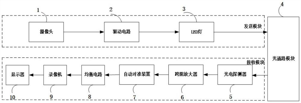
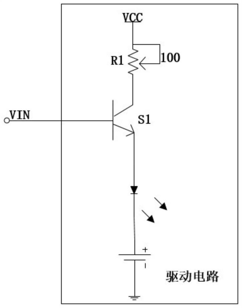
[0051] Such as figure 1 As shown, an ultra-clear video surveillance system based on visible light wireless transmission according to an embodiment of the present invention is mainly composed of a sending module, an optical path module, and a receiving module. Among them, the sending module is used to collect video and drive the video signal through the driving circuit to drive the LED light to be converted into an optical signal, including a camera 1, a driving circuit 2, and an LED light 3, and the receiving module includes a photodetector 5 and a transimpedance amplifier 6 , an automatic alignment device 7 , an equalization circuit 8 , a video recorder 9 , and a display 10 .

[0052] The camera 1, as a signal source, completes the video acquisition and encoding of the actual scene, encodes it into a PAL (Phase Al...


PUM

PropertyMeasurementUnit
Luminous poweraaaaaaaaaa

Abstract

The invention provides a super-definition video monitoring system based on visible light wireless transmission, and belongs to the field of communication. The system comprises a transmitting module, an optical channel module and a receiving module. The transmitting module mainly comprises a camera, a driving circuit and an LED lamp, and the receiving module comprises a photoelectric detector, a trans-impedance amplifier, an automatic alignment device, an equalization circuit, a video recorder and a display. In the receiving module, a photoelectric detector is fixed on an automatic alignment device and is used for completing automatic alignment and receiving optical signals transmitted from an optical channel. The system is applied to wireless video monitoring, the traditional wired video monitoring mode of outdoor and indoor (large shopping malls, office buildings and underground spaces (mines, underground parking lots, subways and underground shopping malls) is changed by utilizing a visible light technology, and over hundred-meter wireless transmission of ultra-definition monitoring videos is realized; and the problems that a monitoring system is high in wired transmission cost and difficult to maintain are solved.

Description

technical field [0001] The invention belongs to the field of visible light communication, and in particular relates to an ultra-clear video monitoring system based on visible light wireless transmission. Background technique [0002] Visible light communication technology has the advantages of no electromagnetic interference, no need to apply for frequency bands, and environmental protection, so it has attracted much attention in recent years. This technology mainly uses the optical signal sent out by fluorescent lamp or LED (Light Emitting Diode) lamp after circuit modulation to transmit information, which can enable LED lamp to perform high-speed communication while illuminating. [0003] With the continuous improvement of production modernization in all walks of life, the requirements for communication means and system functions are increasing. Therefore, it is very necessary to continuously improve the fast, accurate and real-time communication system. Traditional video...

Claims


Application Information

Patent Timeline
IPC IPC(8): H04N7/18H04B10/116
CPCH04B10/116H04N7/18
Inventor 马帅方啸高梦迪张蕴琪陈承儒李世银
Owner CHINA UNIV OF MINING & TECH
Why Eureka
Try Eureka