Die process structure facilitating discharging of fender wheel opening waste and using method

A technology for fenders and scraps, applied in the field of cold stamping dies, can solve the problems of large offset of process parts, the inability of automatic line manipulators to complete the grasping action, and reduce production efficiency, so as to achieve a simple and effective process structure and reduce scrap of parts Quantity, the effect of reducing production costs

Pending Publication Date: 2021-05-14
CHINA FIRST AUTOMOBILE
View PDF13 Cites 0 Cited by
  • Summary
  • Abstract
  • Description
  • Claims
  • Application Information

AI Technical Summary

Problems solved by technology

[0002] In the mass production process of cold stamping dies for automobile outer panels, such as figure 1 As shown, during the upward discharge of a piece of waste material A1 in the middle of the fender mold OP20 wheel mouth, because the distance between the waste material A1 and the process part A is too close after cutting, the process part A will often be biased. At this time, the process part A The position of the OP20 punch is offset, and the automatic line manipulator cannot complete the gripping action, resulting in interruption of continuous production and seriously reducing production efficiency
Sometimes the offset of process parts is too large, which not only has potential safety hazards but also causes process parts to be scrapped, which increases production costs
In addition, if the waste material A1 of this piece is arranged to be discharged downward, it will cause two adjacent pieces of waste material to be discharged upward, which is not worth the candle.

Method used


Image

  • Die process structure facilitating discharging of fender wheel opening waste and using method
  • Die process structure facilitating discharging of fender wheel opening waste and using method
  • Die process structure facilitating discharging of fender wheel opening waste and using method

Examples


Embodiment Construction

[0035] The present invention will be further described in detail below in conjunction with the accompanying drawings and embodiments. It should be understood that the specific embodiments described here are only used to explain the present invention, but not to limit the present invention. In addition, it should be noted that, for the convenience of description, only some structures related to the present invention are shown in the drawings but not all structures.

[0036] Explanation of some terms recorded in the present invention:

[0037] OP10: also known as the first process, refers to the drawing process;

[0038] OP20: also known as the second process, refers to the trimming and punching process;

[0039] OP30: Also known as the third process, it refers to the process of trimming, punching and flanging.

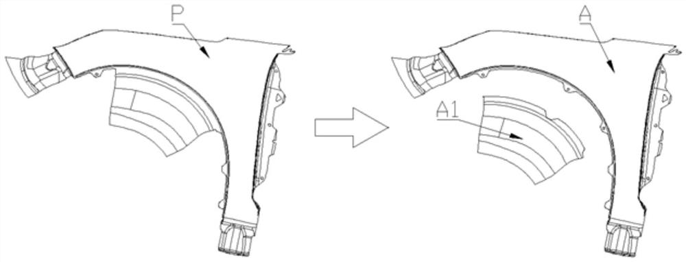
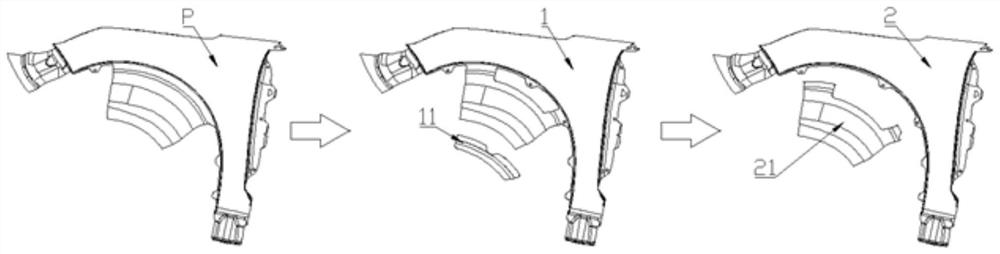
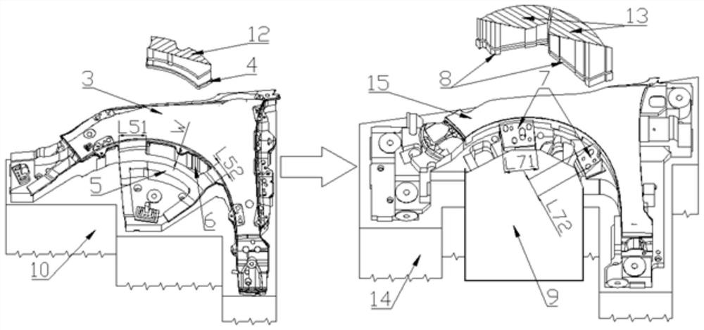
[0040] Such as figure 2 — image 3 As shown, a mold process structure for convenient fender wheel mouth waste discharge, including punching die 6, punching punch ...


PUM


Abstract

The invention discloses a die process structure facilitating discharging of fender wheel opening waste and a using method. The die process structure comprises a punching female die, a punching male die, an OP30 cut-off tool, an OP30 punching and flanging insert and an OP30 waste sliding way. The punching female die is fixed on an OP20 lower die holder through a bolt, the punching male die is fixed on an OP20 upper die holder through a bolt, the OP30 cut-off tool is fixed on an OP30 lower die holder through a bolt, the OP30 punching and flanging insert is fixed on an OP30 upper die holder through a bolt, the OP30 waste sliding way is fixed to the OP30 lower die holder through the bolt, and a position of the OP30 waste sliding way is in lap joint with the back of the OP30 cut-off tool, and is used for bearing OP30 waste. By renovating an OP20 wheel opening part die process structure, under the condition that the number of original dies is not increased, a waste material separation process completed in an original process is divided into two processes to be completed, the problem that the waste is discharged upwards to cause deviation of a process part is solved with an extremely low cost, the production efficiency is improved, potential safety hazards are eliminated, and the production cost is reduced.

Description

technical field [0001] The invention relates to the field of cold stamping dies, in particular to a die process structure and a use method thereof which facilitate the discharge of fender wheel mouth waste. Background technique [0002] In the mass production process of cold stamping dies for automobile outer panels, such as figure 1 As shown, during the upward discharge process of a piece of waste material A1 in the middle of the fender mold OP20 wheel mouth, because the distance between the waste material A1 and the process part A is too close after cutting, the process part A will often be biased. At this time, the process part A The position of the OP20 punch is offset, and the automatic line manipulator cannot complete the gripping action, resulting in interruption of continuous production and seriously reducing production efficiency. Sometimes the offset of process parts is too large, which not only has potential safety hazards but also causes process parts to be scra...

Claims


Application Information

Patent Timeline
Patent Type & Authority Applications(China)
IPC IPC(8): B21D28/34B21D28/26B21D45/00B21D45/04B21D53/88
CPCB21D28/34B21D28/26B21D45/003B21D45/04B21D53/88
Inventor 刘国磊孙树森马天流尹永波邰伟彬胡英杰李响董杰王昊一
Owner CHINA FIRST AUTOMOBILE
Why Eureka
Try Eureka