Optical fiber automatic focusing method and automatic focusing system for laser processing

An automatic focusing and laser processing technology, applied in laser welding equipment, metal processing equipment, manufacturing tools, etc., can solve the problems of poor focusing accuracy, difficult to maintain absolute parallelism, and disadvantageous for large-scale fiber grating array preparation, and achieve positioning accuracy. High, fast focus effects

Active Publication Date: 2021-05-14
SHENZHEN UNIV
View PDF9 Cites 4 Cited by
  • Summary
  • Abstract
  • Description
  • Claims
  • Application Information

AI Technical Summary

Problems solved by technology

However, the existing manual focusing method is not only cumbersome in preliminary preparation and leveling work, but also has poor focusing accuracy, which is not conducive to the preparation of large-scale fiber grating arrays, and hinders the application of fiber grating or microcavity sensors in the field of distributed optical fiber sensing. use
[0005] In addition, after the processing of a section of optical fiber is completed, the next section of optical fiber must be moved to the processing area, and the entire leveling work must be repeated before the preparation of the next section can be carried out; in addition, limited by the performance of the motion mechanism and the vibration isolation capability of the optical platform, the optical fiber It is difficult to maintain absolute parallelism during the translation process, and the laser will deviate from the center of the fiber core if there is a slight jitter, resulting in increased loss and reduced consistency

Method used


Image

  • Optical fiber automatic focusing method and automatic focusing system for laser processing
  • Optical fiber automatic focusing method and automatic focusing system for laser processing
  • Optical fiber automatic focusing method and automatic focusing system for laser processing

Examples


preparation example Construction

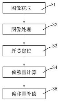
[0157] The existing preparation method does not use segmented sampling and subsequent offset compensation, so the laser position may deviate from the target position on the optical fiber during the preparation process, resulting in a decrease in the performance of the processed structure; at the same time, in the process of array processing It is difficult to guarantee the consistency of each structure in the array, and even the automatic preparation of the array cannot be performed.

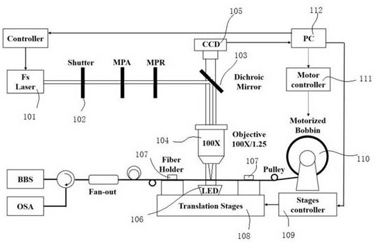
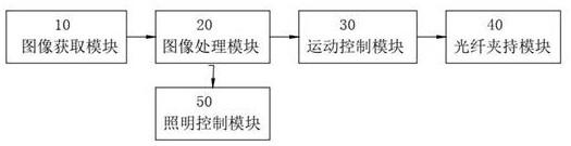
[0158] Further, the motion control module 30 also includes a rotation motion control module 34, such as Figure 8shown. The rotation motion control module 34 is specifically used to rotate the optical fiber, so as to align the target position on the optical fiber at different positions of the multi-core optical fiber, such as the core, to the area to be processed. In this scenario, the rotational motion control module 34 can control the rotation of the optical fiber clamp, for example, the rota...


PUM


Abstract

The invention provides an optical fiber automatic focusing method and an automatic focusing system for laser processing. The optical fiber automatic focusing method is used for performing automatic focusing by comprises the following steps of image acquisition, specifically, acquiring an image of a to-be-processed optical fiber; processing the image to obtain an image edge; obtaining the edge of a fiber core, specifically, performing non-maximum suppression processing and discrete edge connection processing on the image edge to obtain fine upper and lower edges of the fiber core; offset calculation, specifically, calculating the offset according to the upper and lower edges of the fiber core; and offset compensation, specifically, performing compensation according to the information of the offset, so that enabling the laser to be focused at the target position on the optical fiber. According to the optical fiber automatic focusing method and the optical fiber automatic focusing system for the laser processing, automatic optical fiber focusing can be achieved, and the laser is focused at the target position on the optical fiber, the positioning precision is high, the focusing speed is high, and different types of optical fibers can be processed.

Description

technical field [0001] The invention relates to the technical field of processing optical fibers by laser, in particular to an optical fiber automatic focusing method and an automatic focusing system for laser processing. Background technique [0002] Fiber gratings or microcavities can be prepared by laser processing of optical fibers. A fiber grating is a diffraction grating formed by periodically modulating the refractive index of the fiber core in the axial direction. It is a passive filter device. Fiber Bragg grating has a series of excellent performances such as wide reflection bandwidth, small additional loss, small size, easy coupling with optical fiber, compatibility with other optical devices, and not affected by environmental dust. It is more sensitive to changes in the external environment such as laser rate and concentration, so it has been widely used in the field of fiber laser, fiber optic communication and sensing, and is a very important device in the fiel...

Claims


Application Information

Patent Timeline
Patent Type & Authority Applications(China)
IPC IPC(8): B23K26/046B23K26/70G06T7/00G06T7/13G06T7/70
CPCB23K26/046B23K26/702G06T7/0004G06T7/13G06T7/70
Inventor 何俊王义平肖珣周杜斌
Owner SHENZHEN UNIV
Why Eureka
Try Eureka