Woodworking numerical control machining center capable of achieving automatic feeding

A processing center and automatic feeding technology, which is applied in the field of wood processing, can solve the problems of single operation steps of machine tools, affect production efficiency, and high labor intensity, and achieve the effects of high degree of automation, simple structure, and reduced labor intensity

Pending Publication Date: 2021-05-14
BINZHOU COSEN CNC EQUIP TECH
View PDF0 Cites 0 Cited by
  • Summary
  • Abstract
  • Description
  • Claims
  • Application Information

AI Technical Summary

Problems solved by technology

Traditional wood processing is often done in public, with low production efficiency and high labor intensity
Although there are also secondary machine tools for wood processing, these machine tools can only perform a single operation step, and multiple machines are required to complete a product, and manual refueling is required during processing, which affects production efficiency

Method used


Image

  • Woodworking numerical control machining center capable of achieving automatic feeding
  • Woodworking numerical control machining center capable of achieving automatic feeding
  • Woodworking numerical control machining center capable of achieving automatic feeding

Examples


Embodiment Construction

[0032] The following are only specific embodiments of the present invention, but the protection scope of the present invention is not limited thereto, and any changes or substitutions that can be easily conceived by those skilled in the art within the technical scope disclosed in the present invention shall be covered. Within the protection scope of the present invention.

[0033] The words "front", "rear", "inner" and "outer" described in the present invention to describe the relationship between directions are only for the convenience of description of the embodiment, and are not considered to limit the present invention. The "first", "second" and so on are only used for distinguishing descriptions, and should not be understood as indicating or implying relative importance. The fixed connection methods include but are not limited to welding, screwing, clamping, interference fit, and integral molding.

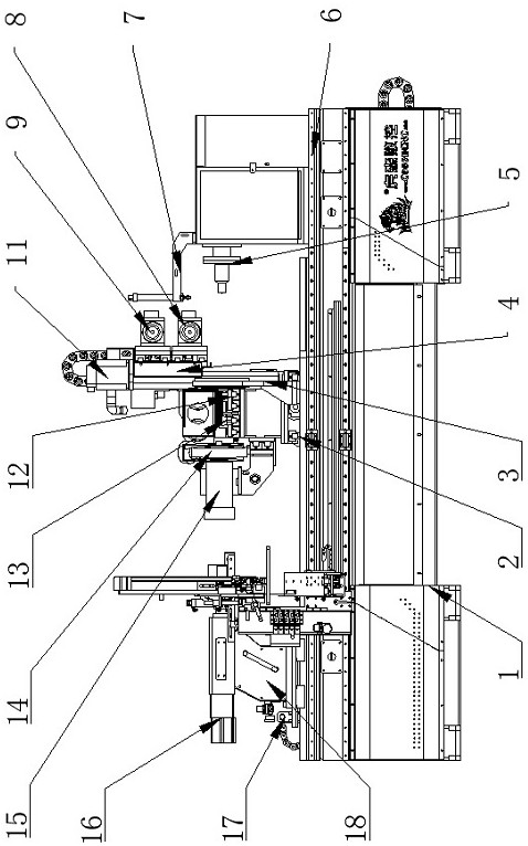
[0034] The "left" referred to below is the side where the tailstock 18 i...


PUM


Abstract

The invention discloses a woodworking numerical control machining center capable of achieving automatic feeding. A lathe bed is provided with a tailstock guided by a tailstock sliding rail and a tool rest guided by an X-axis sliding rail, the lathe bed is provided with a spindle box coaxially arranged with the tailstock, and the tool rest is installed on the X-axis sliding rail. A feeding device is installed on the lathe bed and comprises a feeding frame sliding rail along the lathe bed, a feeding frame is installed on the feeding frame sliding rail in a sliding mode, the feeding frame comprises an installation frame in sliding fit with the feeding frame sliding rail, a stand column is installed on the installation frame in a sliding mode, a vertical adjusting assembly is rotationally installed on the stand column, one end of the vertical adjusting assembly is matched with the stand column, and the other end of the vertical adjusting assembly is matched with the installation frame. A transverse plate with the top provided with a storage assembly is installed at the upper portion of the stand column in a sliding mode. A transverse adjusting assembly and a pneumatic feeding assembly are installed on the two sides of the transverse plate correspondingly, one end of the transverse adjusting assembly is in movable fit with the transverse plate, and the other end of the transverse adjusting assembly is matched with the stand column. The woodworking numerical control machining center capable of achieving automatic feeding is simple in structure, automatic feeding is achieved, the machining efficiency is high, and manpower is saved.

Description

technical field [0001] The invention relates to the technical field of wood processing, in particular to a woodworking numerical control machining center capable of automatic feeding. Background technique [0002] Machining centers are developed from CNC milling machines. The biggest difference from the CNC milling machine is that the machining center has the ability to automatically exchange machining tools. By installing different-purpose tools on the tool magazine, the machining tool on the spindle can be changed through an automatic tool changer in one clamping to achieve a variety of machining. Features. Traditional wood processing is often done in public, with low production efficiency and high labor intensity. Although there are also secondary machine tools for wood processing, these machine tools can only perform a single operation step, and multiple machines are required to complete a product, and manual refueling is required during processing, which affects produ...

Claims


Application Information

Patent Timeline
Patent Type & Authority Applications(China)
IPC IPC(8): B27C9/04B27C5/02B27C5/06B24B27/00B24B41/00B24B41/02
CPCB24B27/0076B24B41/005B24B41/02B27C5/02B27C5/06B27C9/04
Inventor 赵光俊林善龙
Owner BINZHOU COSEN CNC EQUIP TECH
Why Eureka
Try Eureka