
Wire winding device and wire winding method

A winding device and winding technology, applied in the direction of fine working devices, working accessories, stone processing equipment, etc., can solve problems such as impact, main shaft groove damage, steel wire damage, etc.

Pending Publication Date: 2021-05-14
XIAN ESWIN MATERIAL TECH CO LTD +1
View PDF8 Cites 0 Cited by
  • Summary
  • Abstract
  • Description
  • Claims
  • Application Information

AI Technical Summary

Problems solved by technology

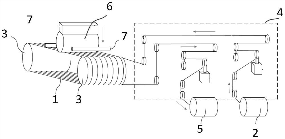
[0003] In the related technology, steel wire winding is mostly manual operation, and the steel wire is wound in the wire groove on the surface of the main shaft by artificially interspersing the steel wire. This winding method has low work efficiency, and the single winding time is about 1 to 2 hours, affecting the overall production capacity of the process; moreover, the manual operation method has poor control stability, resulting in poor quality stability, easy to cause steel wire damage, spindle groove damage, and directly lead to abnormalities such as broken wires, resulting in large product losses

Method used


Image

  • Wire winding device and wire winding method
  • Wire winding device and wire winding method
  • Wire winding device and wire winding method

Examples


Embodiment Construction

[0032] In order to make the purpose, technical solutions and advantages of the embodiments of the present disclosure clearer, the technical solutions of the embodiments of the present disclosure will be clearly and completely described below in conjunction with the accompanying drawings of the embodiments of the present disclosure. Apparently, the described embodiments are some of the embodiments of the present disclosure, not all of them. Based on the described embodiments of the present disclosure, all other embodiments obtained by persons of ordinary skill in the art without creative effort fall within the protection scope of the present disclosure.

[0033] Unless otherwise defined, the technical terms or scientific terms used in the present disclosure shall have the usual meanings understood by those skilled in the art to which the present disclosure belongs. "First", "second" and similar words used in the present disclosure do not indicate any order, quantity or importan...


PUM


Abstract

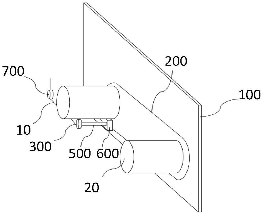
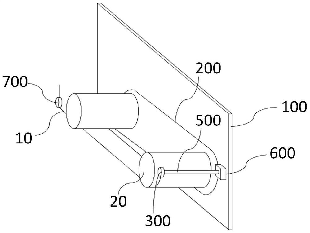
The invention provides a wire winding device and a wire winding method. The wire winding device comprises a supporting part, a wire winding track, a wire winding wheel, a wire supply shaft, an axial movement control part and a controller, wherein one ends of two main shafts are fixed on the supporting part, the winding track is arranged on the supporting part and is a closed annular track that surrounds the peripheries of the two main shafts by a circle, the starting end of a steel wire is arranged on the wire winding wheel, the wire winding wheel is arranged on the wire winding track in a movable mode, the tail end of the steel wire is wound around the wire supply shaft, the axial movement control part is movably arranged on the wire winding track, the wire winding wheel is arranged on the axial movement control part, the axial movement control part is configured to control the wire winding wheel to move in the axial direction of the main shafts, and the controller is used for controlling the motion state of the wire winding wheel and the working state of the axial movement control part. According to the wire winding device and the wire winding mode in the embodiments, the wire winding operation efficiency can be improved, the process productivity can be improved, the operation process is stable, and damage to the steel wire and the main shaft is reduced.

Description

technical field [0001] The invention relates to the technical field of multi-wire cutting, in particular to a wire winding device and a wire winding method. Background technique [0002] Monocrystalline silicon wafers in the semiconductor and solar energy fields mostly use a multi-wire cutting method. By bonding the workpiece to be cut to the feeding mechanism, the workpiece is pushed to a set of parallel steel wire arrays to complete the wafer cutting process. According to whether mortar is used in the cutting process and the type of steel wire, it can be divided into free abrasive cutting method (Free Abrasive Method) and fixed abrasive cutting method (Fixed Abrasive Method). Among them, in the free abrasive cutting method, a straight steel wire is used to reciprocate and wrap around the main body of the equipment to form a parallel line array. Abrasive or mortar is sprayed, and the steel wire drives the mortar or abrasive into the cutting surface of the crystal ingot to ...

Claims


Application Information

Patent Timeline
IPC IPC(8): B28D5/04B28D7/00
CPCB28D5/045B28D5/0064B28D5/0058
Inventor 陈光林
Owner XIAN ESWIN MATERIAL TECH CO LTD
Learn More