
Power factor correction device and power supply

A power factor correction and power technology, which is applied in the direction of output power conversion device, AC power input conversion to DC power output, electrical components, etc., can solve the problem of excessive backflow current, low frequency bandwidth of current loop, and easy current distortion, etc. question

Active Publication Date: 2021-05-14
INVENTCHIP TECH CO LTD
View PDF6 Cites 1 Cited by
  • Summary
  • Abstract
  • Description
  • Claims
  • Application Information

AI Technical Summary

Problems solved by technology

However, when realizing the continuous control of the PFC circuit, the related technology uses a three-input multiplier and a voltage-current loop. However, the frequency bandwidth of the current loop is low, and the current is prone to distortion. Moreover, when the input voltage suddenly drops or drops When the power is turned on, the loop usually does not have time to adjust the pulse width of the control signal, so that the bridgeless PFC generates a large current backflow. On the one hand, the backflow current drains the energy stored in the PFC output capacitor, and on the other hand, the backflow current may be too large and damage the semiconductor power device.

Method used


Image

  • Power factor correction device and power supply
  • Power factor correction device and power supply
  • Power factor correction device and power supply

Examples


Embodiment Construction

[0048]Various exemplary embodiments, features, and aspects of the present disclosure will be described in detail below with reference to the accompanying drawings. The same reference numbers in the figures indicate functionally identical or similar elements. While various aspects of the embodiments are shown in drawings, the drawings are not necessarily drawn to scale unless specifically indicated.

[0049] The word "exemplary" is used exclusively herein to mean "serving as an example, embodiment, or illustration." Any embodiment described herein as "exemplary" is not necessarily to be construed as superior or better than other embodiments.

[0050] In addition, in order to better illustrate the present disclosure, numerous specific details are given in the following specific implementation manners. It will be understood by those skilled in the art that the present disclosure may be practiced without some of the specific details. In some instances, methods, means, component...


PUM


Abstract

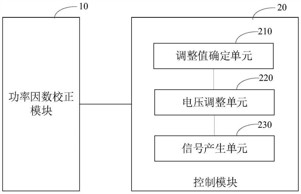
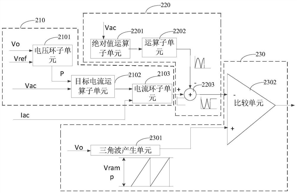
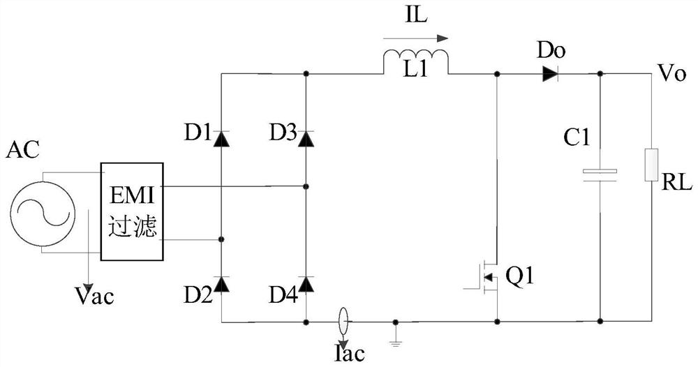
The invention relates to a power factor correction device and a power supply. The power factor correction device comprises a power factor correction module and a control module, wherein the control module is used for outputting a control signal to control a conduction state of a transistor, and the control module comprises an adjustment value determining unit, a voltage adjusting unit and a signal generation unit; the adjustment value determining unit is used for determining a target current and determining an adjustment value according to the target current and the detection current of the inductor in the power factor correction module; the voltage adjusting unit is used for adjusting a feed-forward voltage signal obtained according to the alternating voltage of the input alternating current by using the adjusting value; and the signal generation unit is used for generating a control signal by using the adjusted voltage so as to control the conduction state of the transistor in the power factor correction module. According to the power factor correction device provided by the embodiment of the invention, the loop bandwidth of the PFC is improved, the current distortion is reduced, the THD (Total Harmonic Current Distortion) is reduced, the backward current of the totem-pole PFC is prevented, and the stability and the safety of the PFC are improved.

Description

technical field [0001] The present disclosure relates to the technical field of integrated circuits, in particular to a power factor correction device and a power supply. Background technique [0002] The application of power electronics technology can greatly increase the power density of electric energy conversion devices and effectively reduce the volume and weight of the devices. With the rapid development of power electronics technology, there are more and more power electronic devices, and almost every power electronic device needs to convert AC power into DC power through rectification technology, in order to reduce the mutual influence of load harmonics on the power grid and other equipment , the input current harmonic content and power density of each electronic device need to meet the current harmonic requirements of AC electrical equipment. Therefore, it is of great significance to study a PFC (power factor correction, Power Factor Corrector) converter with high ...

Claims


Application Information

Patent Timeline
IPC IPC(8): H02M1/42H02M7/217
CPCH02M1/4208H02M7/217Y02B70/10
Inventor 叶忠朱丹阳韩启祥
Owner INVENTCHIP TECH CO LTD
Learn More