System and method for suppressing noise in a phase-locked loop circuit

A phase-locked loop and noise technology, applied in the field of frequency signals, can solve problems such as inability to remove the loop filter, reduce the signal quality and performance of the host system, etc.

Active Publication Date: 2005-12-14
GCT SEMICONDUCTOR INC
View PDF0 Cites 1 Cited by
  • Summary
  • Abstract
  • Description
  • Claims
  • Application Information

AI Technical Summary

Problems solved by technology

In fact, the spurious signals are so close to the output frequency (Δf is very small) that they lie within the loop bandwidth of the circuit and ...

Method used


Image

  • System and method for suppressing noise in a phase-locked loop circuit
  • System and method for suppressing noise in a phase-locked loop circuit
  • System and method for suppressing noise in a phase-locked loop circuit

Examples


Embodiment Construction

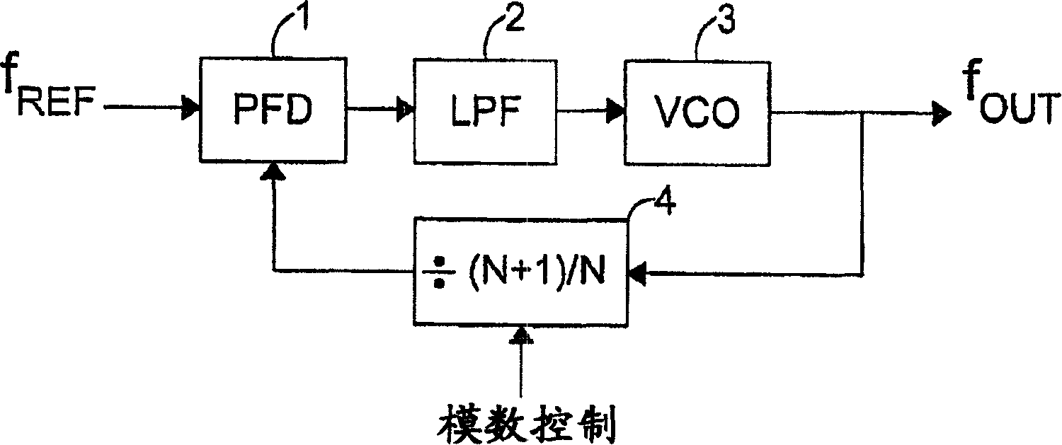
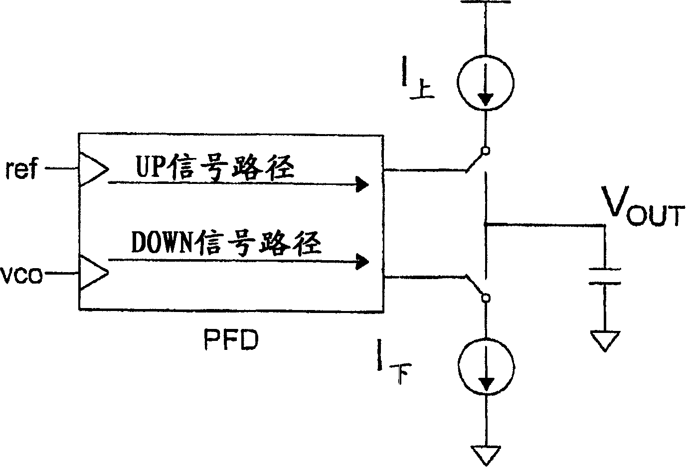
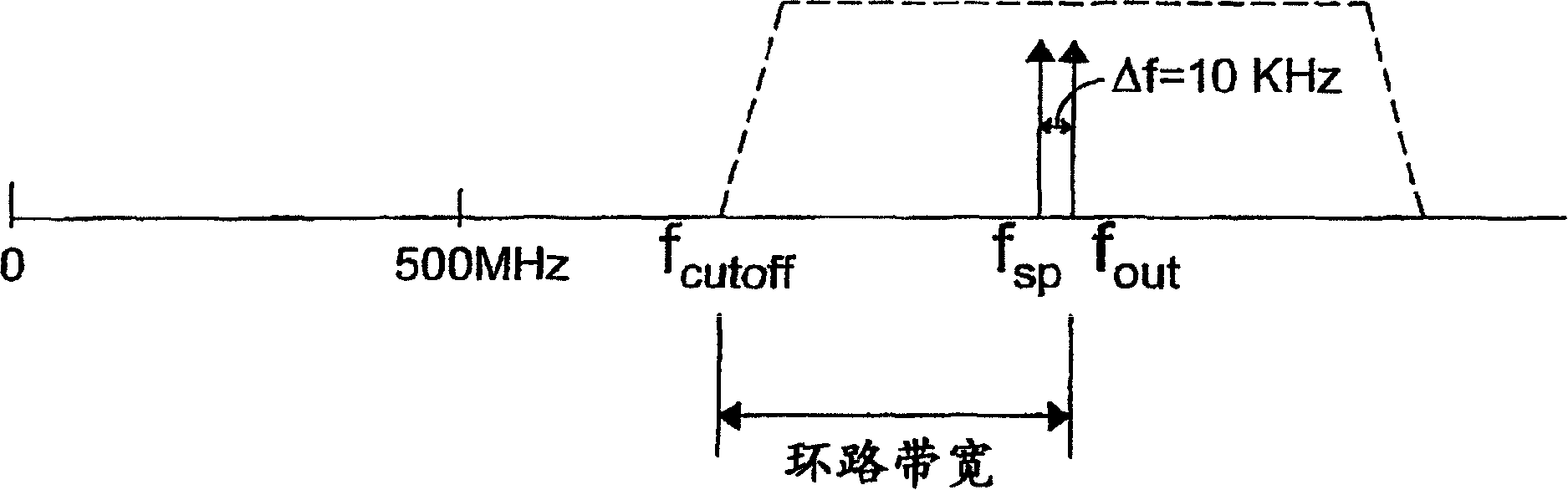
[0031] The present invention includes various embodiments of systems and methods for suppressing noise in phase locked loop circuits. According to one embodiment, the systems and methods suppress noise generated by mismatches associated with charge pumps and phase and frequency detectors. This is accomplished using a sigma-delta modulator that controls a frequency divider in the feedback path of the PLL such that spurious noise components are shifted out of the operating loop bandwidth of the circuit. Other embodiments suppress noise by modulating the reference frequency signal input to the phase and frequency detector. Other embodiments use a combination of the above techniques to suppress noise. With these embodiments, the spurious noise components are kept away from the desired output frequency of the PLL so that they can be removed by the loop filter. As a result, substantial improvements in signal-to-noise ratio and loop bandwidth and proportional reductions in phase no...


PUM


Abstract

Systems and methods for increasing the signal-to-noise ratio of a frequency generator suppress phase noise and noise generated by mismatches in internal generator circuits. This is accomplished using a modulation scheme that moves the spurious noise signal out of the generator's loop bandwidth. When shifted in this manner, the noise signal can be removed entirely or to any desired degree using, for example, filters located along the signal path of the generator. In one embodiment, the sigma-delta modulator controls the value of a swallow divider placed along the feedback path of the phase-locked loop in order to achieve the desired degree of noise rejection. In another embodiment, the reference signal input to the phase locked loop is modulated to achieve noise suppression. In another embodiment, the above forms of modulation are combined in order to achieve the desired frequency offset. With these modulation techniques, the signal-to-noise ratio of the frequency generator can be substantially improved while achieving faster lock times.

Description

technical field [0001] The invention relates to the generation of frequency signals in signal processing systems. Background technique [0002] Phase-locked loop (PLI) circuits have been used in many wired and wireless applications to generate carrier frequency and timing reference signals. [0003] Figure 1(a) shows a PLL typically used in a communication transceiver. The circuit consists of a phase and frequency detector 1, a loop filter 2 and outputs a signal f of the desired frequency out The VCO3. The feedback loop connecting the oscillator to the input of the phase and frequency detector comprises a frequency divider 4 which divides the output of the oscillator by the value (N+1) / N. The analog-to-digital control circuit outputs a signal to the frequency divider for controlling the value N. [0004] In PLLs of the type described above, it is known that there is a trade-off between loop bandwidth and channel spacing. Also know that the channel spacing is the same as...

Claims


Application Information

Patent Timeline
IPC IPC(8): H03L7/06
Inventor 安水皓宋殷濑具利度李正雨朴畯培李京浩
Owner GCT SEMICONDUCTOR INC
Why Eureka
Try Eureka