Overturning type painting equipment for PCB for electrical protection
A technology for PCB board and electrical protection, which is applied in the field of flip-type painting equipment for PCB boards for electrical protection, and can solve problems such as affecting costs, wasting resources, and not being easy to clean
- Summary
- Abstract
- Description
- Claims
- Application Information
AI Technical Summary
Problems solved by technology
Method used
Image
Examples
Embodiment 1
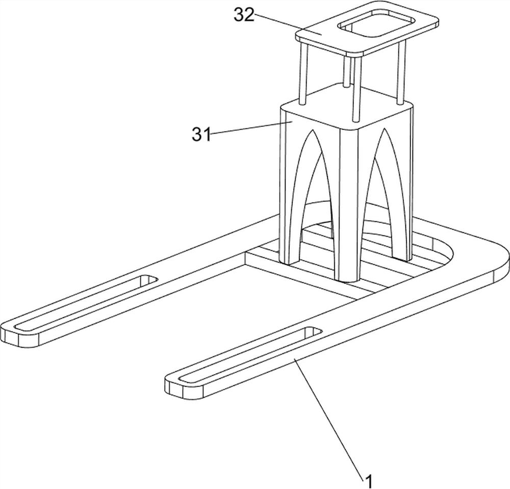
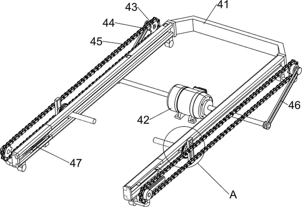
[0073] A flip-type painting equipment for PCB boards for electrical protection, such as figure 1 As shown, it includes a base 1, a support frame 2, a bearing mechanism 3, a moving mechanism 4 and a clamping mechanism 5. Two support frames 2 are provided on the upper side of the base 1, and a bearing mechanism 3 is provided on the upper side of the middle part of the base 1. The support frame 2. A moving mechanism 4 is provided on the upper side. The carrying mechanism 3 cooperates with the moving mechanism 4. The front part of the moving mechanism 4 is provided with a clamping mechanism 5.
[0074] When people are going to paint the PCB board, first put the PCB board into the clamping mechanism 5, then start the moving mechanism 4, the moving mechanism 4 will drive the PCB board to flip and move, and the moving mechanism 4 will drive the clamping mechanism 5 Clamp the PCB board. At this time, people paint the PCB board. When the PCB is painted, close the moving mechanism 4. At...
Embodiment 2
[0076] On the basis of Example 1, such as figure 1 , figure 2 , image 3 , Figure 4 , Figure 5 , Figure 10 with Figure 11 As shown, the carrying mechanism 3 includes a first bracket 31 and a material receiving plate 32 , the base 1 is provided with a first bracket 31 at the rear, and the upper side of the first bracket 31 is provided with a material receiving plate 32 .
[0077] When people are going to paint the PCB board, first put the PCB board into the clamping mechanism 5, the first bracket 31 and the material receiving plate 32 will cooperate with the supporting frame 2 to support the moving mechanism 4, start the moving mechanism 4, and move The mechanism 4 will drive the PCB board to flip and move, and the clamping mechanism 5 will clamp the PCB board. People can paint the PCB board. After the PCB board is painted, close the moving mechanism 4. At this time, the moving mechanism 4 will stop moving. Clamping mechanism 5 will no longer clamp the PCB board, peo...
Embodiment 3
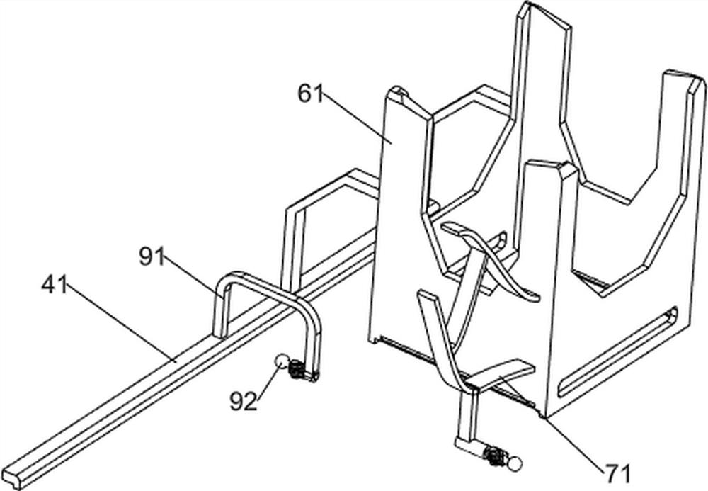
[0083] On the basis of Example 2, such as figure 1 , Image 6 , Figure 7 , Figure 8 , Figure 9 , Figure 10 with Figure 11 As shown, a feeding mechanism 6 is also included, and the feeding mechanism 6 includes a storage box 61, a first connecting rod 62, a first material blocking plate 63, a second compression spring 64, a second clamping plate 65, a second connection Rod 66, the third compression spring 67, the rotating rod 68, the second material retaining plate 69 and the clamping plate 610, the upper side of the fixed frame 41 rear part is provided with a storage box 61, and the storage box 61 bottom sliding type is provided with a first connecting rod 62. A first material blocking plate 63 is provided on the lower side of the rear part of the first connecting rod 62, and the first material blocking plate 63 is slidably connected with the storage box 61. A second compression spring 64 is wound around the upper side of the rear part of the first connecting rod 62. ...
PUM
 Abstract
Description
Claims
Application Information
 - R&D
- Intellectual Property
- Life Sciences
- Materials
- Tech Scout
- Unparalleled Data Quality
- Higher Quality Content
- 60% Fewer Hallucinations
Browse by: Latest US Patents, China's latest patents, Technical Efficacy Thesaurus, Application Domain, Technology Topic, Popular Technical Reports.
© 2025 PatSnap. All rights reserved.Legal|Privacy policy|Modern Slavery Act Transparency Statement|Sitemap|About US| Contact US: help@patsnap.com


