Metal pipeline welding device

A welding device and metal pipeline technology, applied in welding equipment, metal processing, welding equipment, etc., can solve problems such as temperature rise and low degree of automation

Active Publication Date: 2021-05-18
芜湖沸点智能装备有限公司
View PDF8 Cites 1 Cited by
  • Summary
  • Abstract
  • Description
  • Claims
  • Application Information

AI Technical Summary

Problems solved by technology

[0005] Aiming at the deficiencies of the prior art, the present invention provides a metal pipe welding device, which solves the problem of low automation of the existing metal welding device, realizes the function of automatically clamping and fixing the metal pipe after placing it, and can satisfy The fixing of metal pipes of different specifications improves the adaptability of the device, can easily release the fixing of metal pipes, has better cooling ability, and can avoid the temperature rise of metal pipes during welding

Method used


Image

  • Metal pipeline welding device
  • Metal pipeline welding device
  • Metal pipeline welding device

Examples


Embodiment 1

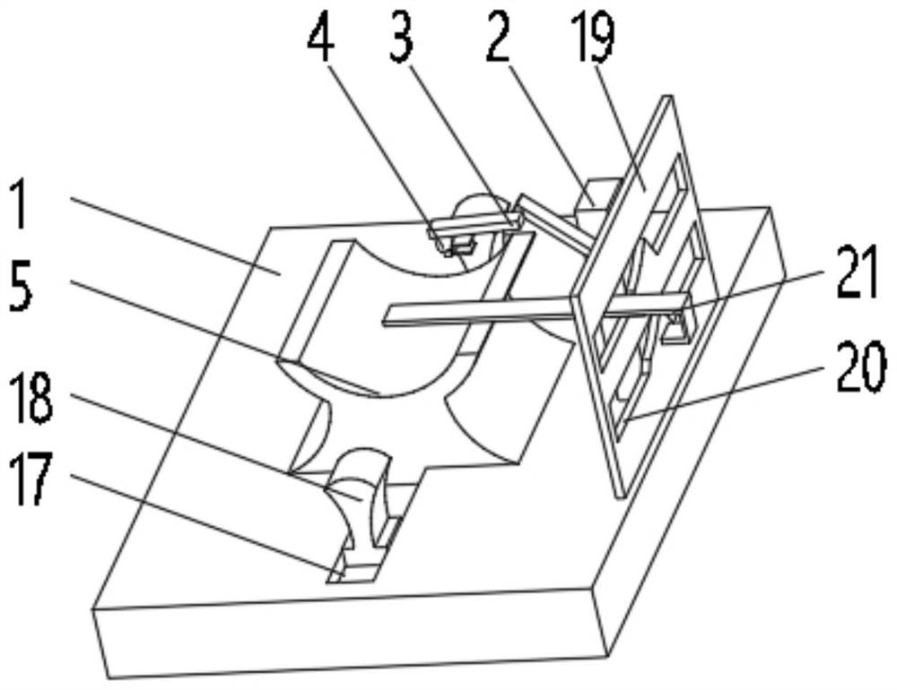
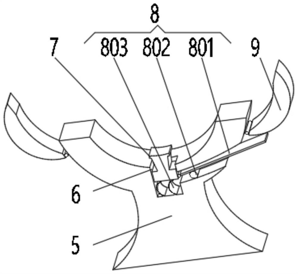
[0033] see Figure 1-2 , the present invention provides a technical solution: a metal pipe welding device, including a processing table 1, the top of the processing table 1 is fixedly connected with a support rod 2, and the top of the support rod 2 is connected with a welding head 4 through a deflection connecting rod 3, and the processing The middle position of the top of the table 1 is fixedly connected with the welding base 5, and the top of the welding base 5 is uniformly provided with a trigger groove 6, one side of the trigger groove 6 runs through the welding base 5, and a lifting block is slidingly connected between the two sides of the inner wall of the trigger groove 6 7. A trigger device 8 is installed on one side of the lifting block 7 inside the trigger groove 6, and a clamping device 9 is installed on both sides of the welding base 5, and the clamping device 9 is connected to the trigger device 8.

[0034] The trigger device 8 includes a seesaw 801, which is rota...

Embodiment 2

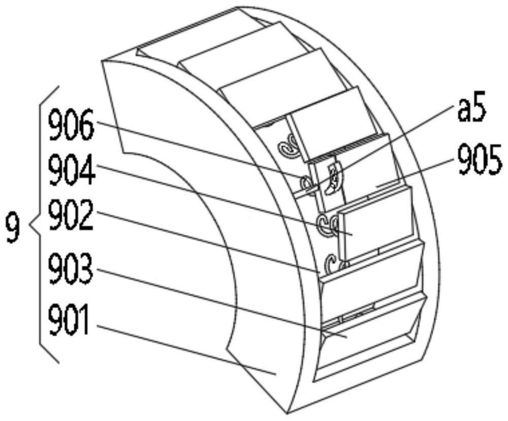
[0039]see Figure 1-4 , the present invention provides a technical solution: on the basis of Embodiment 1, the clamping device 9 includes a rubber clamp 901, and the side of the rubber clamp 901 away from the lifting block 7 is provided with an extrusion groove 902, and the extrusion groove 902 An extruding plate 903, a limiting plate 904 and a control plate 905 are installed between the two sides of the inner wall, and the extruding plate 903, the limiting plate 904 and the control plate 905 are all rotatably connected with the inner wall of the extruding groove 902, and the extruding groove 902 Squeeze springs 906 are evenly installed on one side of the inner wall.

[0040] The control board 905 includes a hard board a1, one side of the hard board a1 is fixedly connected with an elastic coil a2, the bottom of the elastic coil a2 is fixedly connected with a counterweight a4 through a traction rope a3, and one side of the inner wall of the extrusion groove 902 Rotationally co...

Embodiment 3

[0044] see Figure 1-6 , the present invention provides a technical solution: on the basis of Embodiment 1, a funnel hole 10 is evenly opened on the bottom of the lifting block 7, and an atomization device 11 is installed inside the funnel hole 10, and the inside of the trigger groove 6 is located in the lifting block 7 The bottom of the slapping fan blade 111 is filled with cooling liquid, and the atomizing device 11 includes a flapping fan blade 111, which is evenly installed inside the funnel hole 10, and the outer side of the flapping fan blade 111 is provided with a mounting ring 112, and the mounting ring 112 and the The inner wall of the funnel hole 10 is slidably connected, and the top of the flapping fan blade 111 is provided with an atomizing hole 113 , and an atomizing plate 114 is evenly installed inside the atomizing hole 113 .

[0045] The bottom of the atomizing plate 114 is uniformly provided with magnet slots 12 , and both sides of the magnet slot 12 are provi...


PUM


Abstract

The invention discloses a metal pipeline welding device which comprises a machining table. A supporting rod is fixedly connected to the top of the machining table; a welding head is connected to the top of the supporting rod through a deflection connecting rod; a welding base is fixedly connected to the middle position of the top of the machining table; trigger grooves are evenly formed in the top of the welding base; one side of each trigger groove penetrates through the welding base; a lifting block is slidably connected between the two sides of the inner walls of the trigger grooves; and a trigger device is installed in each trigger groove. The metal pipeline welding device provided by the invention relates to the technical field of metal machining equipment. According to the metal pipeline welding device, the purpose of improving the automation degree of the welding device is achieved, the function of automatic clamping and fixing after metal pipes are placed is achieved, fixing of the metal pipes of different specifications can be met, the adaptability degree of the device is improved, fixing of the metal pipes can be conveniently relieved, the good cooling capacity is achieved, and temperature rise during metal pipe welding can be avoided.

Description

technical field [0001] The invention relates to the technical field of metal processing equipment, in particular to a metal pipeline welding device. Background technique [0002] Welding tooling is an indispensable process equipment in the process of large-scale welding production. It can ensure the relative position of welding, and has a non-negligible effect on improving labor productivity, reducing labor production intensity, and improving quality accuracy. Currently, it is classified according to the power source. , can be mainly divided into pneumatic tooling, electric tooling and hybrid tooling. In the daily welding construction process of ordinary metal pipes or seamless steel pipes, various welding methods such as butt joints and circumferential welding of seamless steel pipes require two parts to be welded. The interface surface of the seamless steel pipe is flush and the center line of the steel pipe is aligned. [0003] However, the existing metal pipe welding de...

Claims


Application Information

Patent Timeline
Patent Type & Authority Applications(China)
IPC IPC(8): B23K31/02B23K37/053B23K37/00
CPCB23K31/02B23K37/053B23K37/003B23K2101/06Y02P70/10
Inventor 不公告发明人
Owner 芜湖沸点智能装备有限公司
Why Eureka
Try Eureka