
Variable-torque automatic bending steel belt welding equipment

A technology of welding equipment and variable torque, which is applied to other manufacturing equipment/tools, manufacturing tools, etc., can solve problems such as difficulty in ensuring quality stability, repeatability accuracy, and poor production consistency of packing belts.

Pending Publication Date: 2021-05-18
TANGSHAN COLLEGE
View PDF0 Cites 1 Cited by
  • Summary
  • Abstract
  • Description
  • Claims
  • Application Information

AI Technical Summary

Problems solved by technology

Hydraulically driven bending can generate powerful thrust, but it is mainly based on the bending model. The thrust of the hydraulic linear motion makes the bent mechanism deform according to the shape of the bending model. In order to prevent the hydraulic thrust cylinder rod from being affected by the lateral Oil leakage occurs due to force, so hydraulic drive is often used for linear thrust. Manual operation leads to large error in the position of the bending point, and it is difficult to guarantee the accuracy of repetition.
The welding position and welding strength are inconsistent, resulting in poor production consistency of packing belts, and it is difficult to guarantee quality stability
When switching production between specifications with different lengths and thicknesses of strapping belts, adjustments are required, which takes a long time to adjust the tooling

Method used


Image

  • Variable-torque automatic bending steel belt welding equipment
  • Variable-torque automatic bending steel belt welding equipment
  • Variable-torque automatic bending steel belt welding equipment

Examples


Embodiment Construction

[0027] The present invention will be further described below in conjunction with the examples.

[0028] The following examples are used to illustrate the present invention, but cannot be used to limit the protection scope of the present invention. The conditions in the embodiment can be further adjusted according to the specific conditions, and the simple improvement of the method of the present invention under the premise of the concept of the present invention belongs to the protection scope of the present invention.

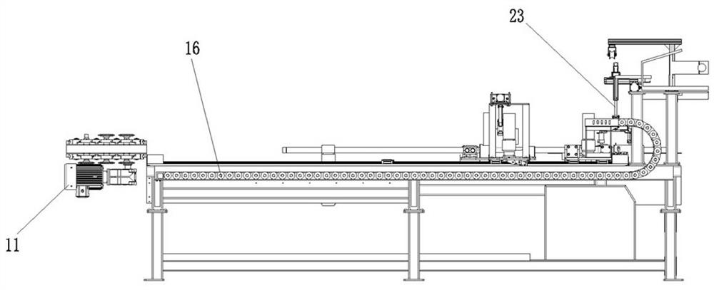
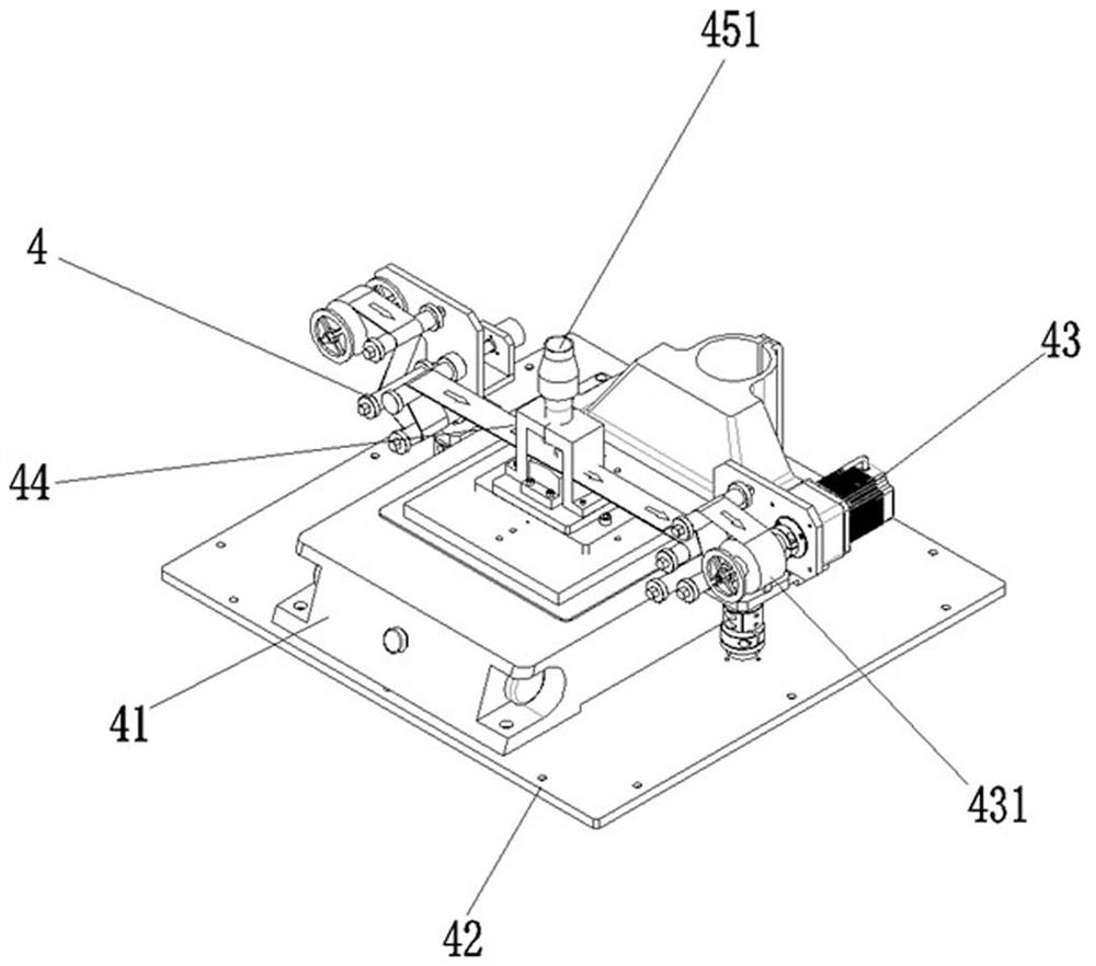
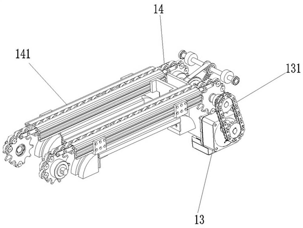
[0029] see Figure 1-7 , the present invention provides a welding equipment for automatically bending steel strips with variable torque, which includes a straightening and conveying assembly 1, a cutting assembly 2, a hydraulic bending assembly 3, and a welding assembly 4. The straightening and conveying assembly 1 includes a straightening adjustment motor 11, a straightening Straight machine 12, straightening adjustment knob 121, cable motor 13, cable transm...


PUM


Abstract

The invention discloses variable-torque automatic bending steel belt welding equipment, and belongs to the field of bending steel belt welding equipment. The variable-torque automatic bending steel belt welding equipment comprises a straightening and conveying assembly, a cutting assembly, a hydraulic bending assembly and a welding assembly. The variable-torque automatic bending steel belt welding equipment is characterized in that a straightening machine is arranged, so that steel is effectively made to rotate leftwards and rightwards through a straightening adjusting knob in the straightening machine to be straightened; a straightening adjusting motor is used for driving a gear in the straightening machine, and straightened steel can be moved through the rotating gear, so that mechanical automatic bending and automatic welding are achieved, the manual workload can be replaced, the speed is high, and the efficiency is high; a cable motor is arranged, so that a motor gear beside the cable motor can be effectively made to rotate; through connection of a cable drag chain, a driven gear behind a cable transmission gear rotates, so that an auxiliary cable drag chain nested outside the driven gear moves, and the straightened steel is conveyed to the cutting assembly through a connecting plate to be cut; and the variable-torque automatic bending steel belt welding equipment can be effectively compatible with steel belts of various specifications and lengths.

Description

technical field [0001] The invention belongs to the technical field of bending steel strip welding equipment, and in particular relates to a torque-variable automatic bending steel strip welding equipment. Background technique [0002] Steel belt has a wide range of applications. Welded pipe packaging is an important process after the production of welded pipes. The packaging belt used for packaging is hexagonal. Generally, the packaging belt is surrounded into a hexagonal shape before packaging. For the packaging of different products, the length of the steel belt is different, and the requirements for the position of the bending point of the packaging belt are also different. In addition, the packaging belt is not an absolutely linear steel belt structure when it is bent. [0003] Most of the current bending methods are to manually mark the steel strip, then manually put it into the bending device for bending, and then perform manual welding after bending. The driving form...

Claims


Application Information

Patent Timeline
IPC IPC(8): B23P23/00
CPCB23P23/00
Inventor 唐永晨葛鼎新孙树建李杰李贺龙李博华郝晶晶
Owner TANGSHAN COLLEGE
Learn More