High-strength crankshaft for three-cylinder high-pressure plunger pump

A high-pressure plunger pump, high-strength technology, applied in the direction of crankshaft, shaft, pump, etc., can solve problems such as crankshaft fracture, failure to consider the direction of pump crankshaft torque input and output, journal wear, etc.

Pending Publication Date: 2021-05-18
上海清力源流体科技有限公司
View PDF0 Cites 0 Cited by
  • Summary
  • Abstract
  • Description
  • Claims
  • Application Information

AI Technical Summary

Problems solved by technology

[0004] Secondly, the crank arm design of the existing high-pressure plunger pump crankshaft is thin, and the difference in torque input and output directions between the pump crankshaft and the internal combustion engine crankshaft has not been considered, so the surface quenching heat treatment process of the traditional internal combustion engine crankshaft has to be used to prevent the crankshaft from breaking The risk of failure, which will undoubtedly increase the complex heat treatment process of the crankshaft;
[0005] And because it needs to keep running at all times during use, the pump crank bearing for high-pressure plunger pumps is subjected to 7X24 hours of high-frequency reciprocating inertial force, rotational inertial force, hydraulic reaction force of the fluid being conveyed, and the resultant moment generated by these forces , so not only is it twisted, but it also bends
Therefore, any improper design, material selection, and manufacturing of the crankshaft for high-pressure plunger pumps can easily cause crankshaft fracture and journal wear, resulting in crankshaft failure.
[0006] The combined effect of the above-mentioned many aspects leads to the high cost of a single product of the high-pressure plunger pump crankshaft. Therefore, it is an urgent need to invent a crankshaft for high-pressure plunger pumps with simple design, compact structure, complete functions, and convenient disassembly and maintenance. the puzzle

Method used


Image

  • High-strength crankshaft for three-cylinder high-pressure plunger pump
  • High-strength crankshaft for three-cylinder high-pressure plunger pump
  • High-strength crankshaft for three-cylinder high-pressure plunger pump

Examples


Embodiment Construction

[0031] The present invention will be described in further detail below in conjunction with the accompanying drawings.

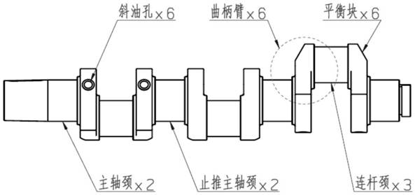
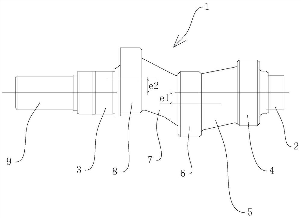
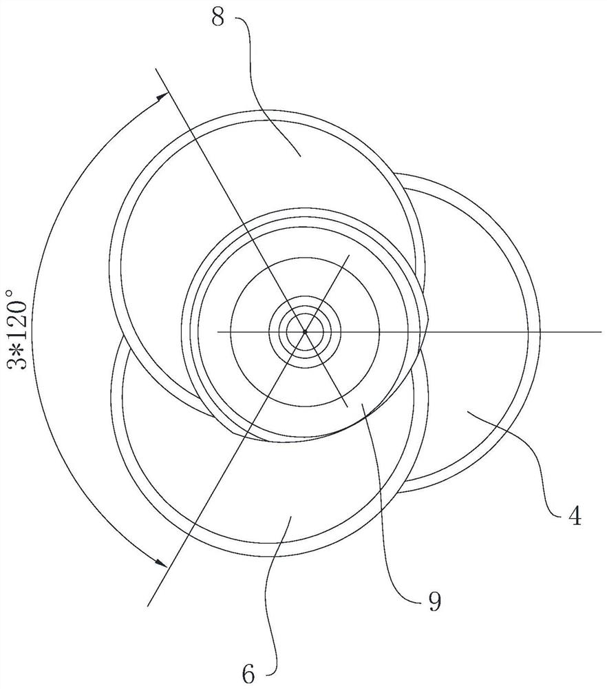
[0032] refer to figure 2 , which is a high-strength crankshaft for a three-cylinder high-pressure plunger pump disclosed in the present invention, includes an output end 2 and an input end 3 respectively provided at both ends of the crankshaft body 1, and the output end 2 is connected to the direction of the input end 3 with first Connecting pin 4, first crank arm 5, second connecting pin 6, second crank arm 7 and third connecting pin 8, first connecting pin 4, second connecting pin 6 and third connecting pin The axis lines of 8 are staggered at 120°, and the first connecting pin journal 4, the first crank arm 5, the second connecting pin journal 6, the second crank arm 7, the third connecting pin journal 8 and the crankshaft body 1 are integrally formed .

[0033] refer to figure 2 , the input end 3 is connected with a thrust main journal 9 . The outpu...


PUM


Abstract

The invention relates to a high-strength crankshaft for a three-cylinder high-pressure plunger pump, and relates to the technical field of high-pressure plunger pumps. The high-strength crankshaft comprises a crankshaft body, the two ends of the crankshaft body are provided with an output end and an input end correspondingly, a first connecting rod neck, a first crank arm, a second connecting rod neck, a second crank arm and a third connecting rod neck are sequentially connected in the direction from the output end to the input end, and the axis of the first connecting rod neck, the axis of the second connecting rod neck and the axis of the third connecting rod neck are arranged in a 120-degree spaced and staggered manner. The input end is connected with a thrust main journal. The high-strength crankshaft has the advantages of being compact in mechanism and complete in function.

Description

technical field [0001] The invention relates to the technical field of high-pressure plunger pumps, in particular to a high-strength crankshaft for a three-cylinder high-pressure plunger pump. Background technique [0002] The existing high-pressure plunger pump crankshaft still continues the design route of the traditional internal combustion engine crankshaft. figure 1 The crankshaft for a high-pressure plunger pump shown is mainly composed of five main journals, thrust main journals, connecting rod journals, balance weights, and crank arms for connecting the main journals, thrust main journals, and connecting rod journals. The main parts are assembled. [0003] However, the power input and output of the three-cylinder high-pressure plunger pump crankshaft is actually different from that of the internal combustion engine crankshaft. The traditional internal combustion engine crankshaft converts the gas power transmitted from the piston and connecting rod assembly into tor...

Claims


Application Information

Patent Timeline
IPC IPC(8): F16C3/06
CPCF16C3/06F16C2360/42
Inventor 周江明宋湘文
Owner 上海清力源流体科技有限公司
Why Eureka
Try Eureka