Contact rail spatial position and abrasion measuring method based on image processing

A technology of spatial position and measurement method, applied in image data processing, measurement device, image enhancement, etc., can solve problems such as low efficiency and inability to guarantee the accuracy of measurement data.

Pending Publication Date: 2021-05-18
GUANGZHOU METRO GRP CO LTD +1
View PDF4 Cites 0 Cited by
  • Summary
  • Abstract
  • Description
  • Claims
  • Application Information

AI Technical Summary

Problems solved by technology

[0005] The object of the present invention is: in order to solve the problem that the prior art uses track ruler and vernier ruler to measure the spatial position and wear of the contact rail, the efficiency is low, and the accuracy of the measurement data cannot be guaranteed. The present inve

Method used


Image

  • Contact rail spatial position and abrasion measuring method based on image processing
  • Contact rail spatial position and abrasion measuring method based on image processing
  • Contact rail spatial position and abrasion measuring method based on image processing

Examples


Embodiment 1

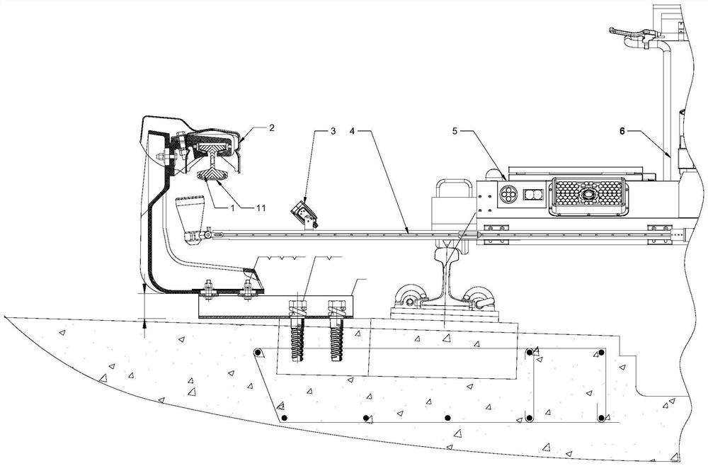
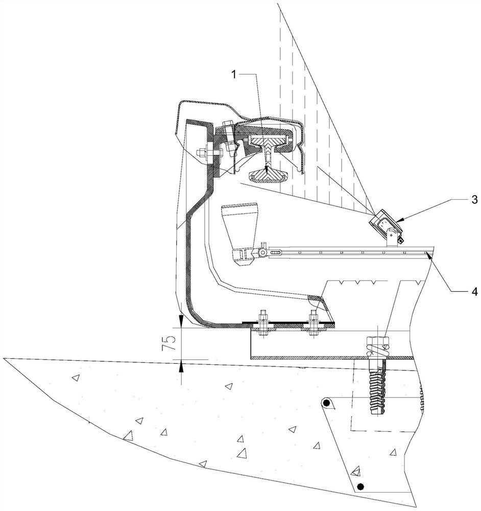
[0052] see Figure 1-7 , the present embodiment provides a method for measuring the spatial position and wear of a contact rail based on image processing, comprising the following steps:

[0053] S1: Acquire images: perform laser three-dimensional imaging on the contact rail 1, and obtain the imaging plan of the contact rail 1 and its protective cover 2;

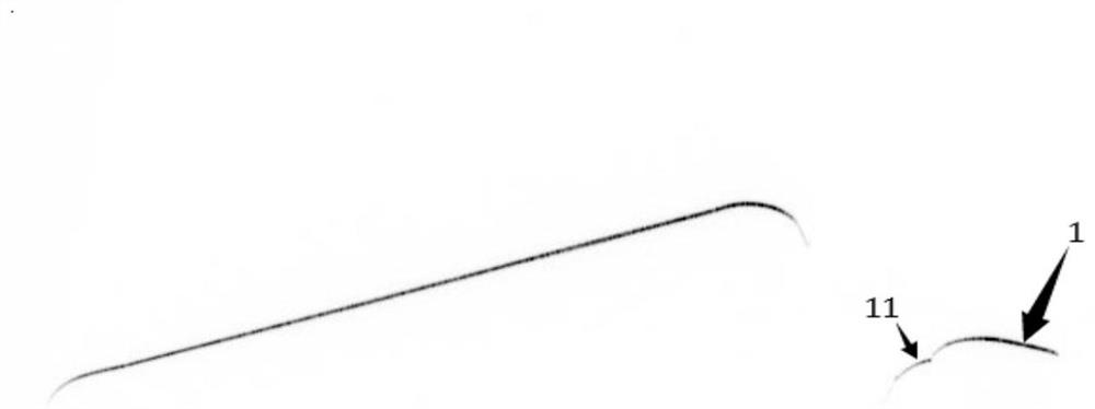
[0054] S2: Data conversion: extract the center line of the laser stripe in the imaging plane, and convert the imaging plane data into 3D point data, specifically:

[0055] The center line of the laser stripe in the imaging plane is extracted by using the optimized gray-scale center of gravity method, and then the imaging plane data is converted into 3D point data according to the calibration parameters of the detection camera 3. Since the laser stripe has a certain width, the laser stripe center line can be extracted. Make the data unique and facilitate subsequent data analysis and calculation; convert the imaging plane dat...


PUM


Abstract

The invention relates to the technical field of contact rail detection, is used for quickly detecting the spatial position of a contact rail and the abrasion loss of a contact surface in real time, and discloses a contact rail spatial position and abrasion measurement method based on image processing, which comprises the following steps: S1, carrying out laser three-dimensional imaging on the contact rail to obtain an imaging plane graph; S2, extracting a laser stripe center line in the imaging plane graph, converting imaging plane graph data into 3D point data, and performing coordinate conversion to obtain a spatial position of the contact rail; S3, obtaining a plurality of coordinate points of the bottom surface of the contact rail from the step S2, and fitting to obtain a linear equation of the bottom surface: ax + by + c = 0; S4, setting the point A as a feature point through an image method; S5, solving the distance from A to the bottom surface, namely the residual height; S6, solving the difference value between the residual height and the standard height, and obtaining the abrasion value of the contact rail. According to the invention, the problems that in the prior art, a track ruler and a vernier scale are adopted for measuring the space position and abrasion of the contact rail, efficiency is low, and the accuracy of measured data cannot be guaranteed are solved.

Description

technical field [0001] The invention relates to the technical field of contact rail detection, in particular to a method for measuring the spatial position and wear of a contact rail based on image processing. Background technique [0002] The contact rail is a device that transmits electrical energy to electric traction vehicles in subways and urban rail transit systems. The contact rail system is mainly composed of steel-aluminum composite rails (including aluminum rail bodies and stainless steel strips), expansion joints, end elbows and other related components and insulation. The supporting device is composed of a supporting device to provide electric energy for the electric locomotive, and the transmission of electric power is realized through the contact between the collector shoe of the electric passenger car and the composite rail. [0003] The contact rail transmits electric energy to the vehicle through the collector shoe. According to the different ways of collect...

Claims


Application Information

Patent Timeline
IPC IPC(8): G01B11/00G01N21/95G06T7/521
CPCG01B11/002G01N21/95G06T7/521G06T2207/10028
Inventor 刘兰金辉冯超邓桂棠谭冬华邱启盛蒋中志柳恩恩李科杨杰王春来王海威黄森
Owner GUANGZHOU METRO GRP CO LTD
Why Eureka
Try Eureka