
Vehicle auxiliary driving system and method based on unmanned aerial vehicle road perception

A vehicle assistance and driving system technology, applied in the direction of motor vehicles, control/regulation systems, vehicle position/route/height control, etc., can solve the problems of few fusion processing, inability to detect road conditions, and difficulty in determining real-time traffic conditions, etc. question

Active Publication Date: 2021-05-18
GUANGZHOU UNIVERSITY
View PDF9 Cites 5 Cited by
  • Summary
  • Abstract
  • Description
  • Claims
  • Application Information

AI Technical Summary

Problems solved by technology

However, this method has a big limitation that the sensors are often fixedly installed on the vehicle body, and the collected road condition information is limited to the surroundings of the vehicle body, making it difficult to determine the real-time traffic conditions that are far away from the vehicle
At the same time, due to the limited viewing angle of the sensor fixed on the vehicle, it can only realize information collection within a fixed direction range. When there are obstacles or other vehicles blocking it, it is impossible to detect the road conditions in the blind spot of sight, and it is difficult to assist the driver to navigate the route. Planning and Security Alerts
[0003] On the other hand, in the existing UAV-assisted vehicle driving systems, the road condition information obtained by the UAV is rarely fused with the road condition information obtained by the vehicle itself.
[0004] Usually, the energy carried by the UAV itself is limited. How to make the UAV fly in the air for a longer time is a problem that cannot be ignored. In the past UAV-assisted vehicle path planning methods, the energy loss of the UAV was rarely considered, and Most of the existing route planning methods determine the starting point and the ending point, and search from the starting point to the ending point to determine the driving path of the target vehicle. However, when the target vehicle is driving between urban roads, the road condition information often changes rapidly and dynamically with time, so The trajectory change of the target vehicle is often caused by the change of obstacles (such as the sudden deceleration of the vehicle in front), and is not static. Therefore, the existing auxiliary vehicle driving technology lacks UAV-assisted vehicle driving process, which can ensure the quality of road condition information while A solution that can reduce the energy consumption of UAV flight as much as possible

Method used


Image

  • Vehicle auxiliary driving system and method based on unmanned aerial vehicle road perception
  • Vehicle auxiliary driving system and method based on unmanned aerial vehicle road perception
  • Vehicle auxiliary driving system and method based on unmanned aerial vehicle road perception

Examples


Embodiment 1

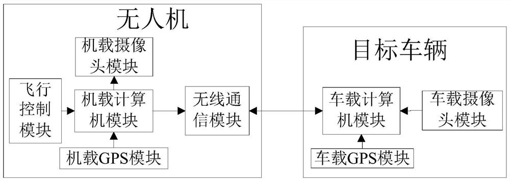
[0062] Such as figure 1 As shown, the present embodiment provides a vehicle assisted driving system based on UAV road perception, the system is provided with a UAV and a target vehicle; wherein the UAV is provided with an airborne controller, an airborne camera module, an Wireless communication module, flight control module and airborne GPS (global positioning system) module; The target vehicle is provided with vehicle-mounted controller, vehicle-mounted camera module, vehicle-mounted wireless communication module and vehicle-mounted GPS (global positioning system) module; The on-board camera module, on-board wireless communication module, flight control module, and on-board GPS module are connected; the on-board controller is connected to the on-board camera module, on-board wireless communication module, and on-board GPS module; the on-board wireless communication module communicates with the on-board wireless Module wireless connection;

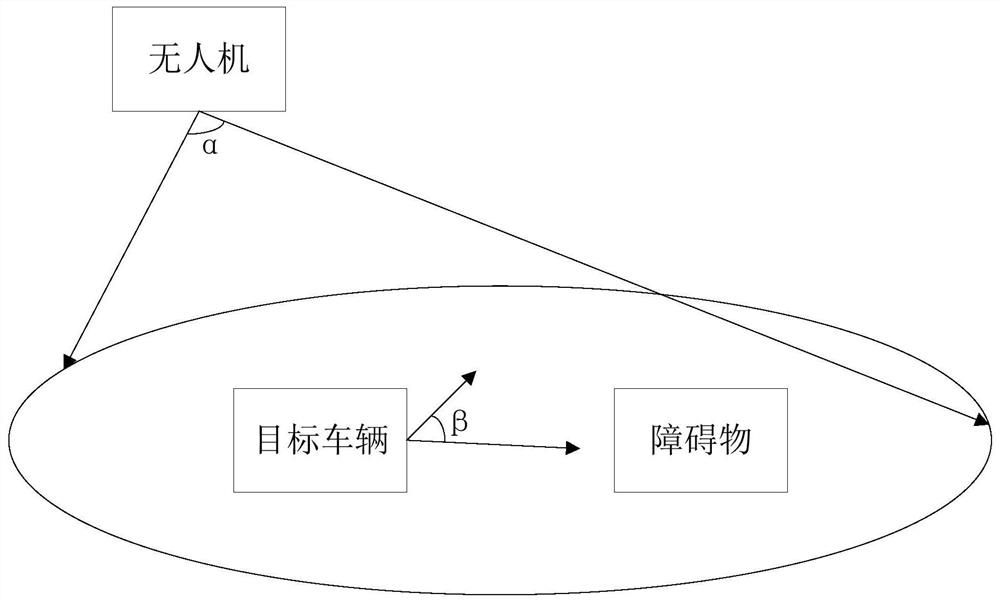
[0063] Such as figure 2 As shown...

Embodiment 2

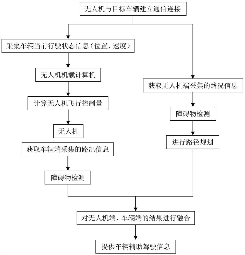
[0066] Such as image 3 As shown, the present embodiment also provides a method for controlling a vehicle assisted driving system based on UAV road perception, the method comprising the following steps:

[0067] S1: The UAV S establishes a communication connection with the target vehicle D, and the UAV transmits the first road condition information around the target vehicle captured by the onboard camera module to the on-board controller of the target vehicle; The location information of the drone is transmitted to the onboard controller of the drone. The UAV is lifted to a preset height through the flight control module, and the on-board camera module looks down at the target vehicle at a preset inclination angle; by calibrating the on-board camera module, the distance between the image pixels and the actual road length can be obtained. relationship, thereby reducing the error of environmental perception. In this embodiment, the preset height is set to 10 meters, and the pr...


PUM


Abstract

The invention discloses a vehicle auxiliary driving system and method based on unmanned aerial vehicle road perception. The vehicle auxiliary driving system is provided with an unmanned aerial vehicle and a target vehicle, wherein the unmanned aerial vehicle comprises a UAV-mounted controller, a UAV-mounted camera module, a UAV-mounted wireless communication module, a flight control module and a UAV-mounted GPS module; the target vehicle comprises a vehicle-mounted controller, a vehicle-mounted camera module, a vehicle-mounted wireless communication module and a vehicle-mounted GPS module; the UAV-mounted wireless communication module is wirelessly connected with the vehicle-mounted wireless communication module; the UAV-mounted camera module collects first road condition information in front of and around the target vehicle; the UAV-mounted GPS module locates a position of the unmanned aerial vehicle; the UAV-mounted controller calculates a position and a speed of the unmanned aerial vehicle; the vehicle-mounted camera module collects second road condition information in front of the target vehicle; the vehicle-mounted controller processes the first road condition information and the second road condition information; and the vehicle-mounted GPS module positions the position of a target vehicle. According to the vehicle auxiliary driving system and the method, the unmanned aerial vehicle is introduced into the vehicle auxiliary driving system for road perception, and the situation perception capability is improved.

Description

technical field [0001] The invention relates to the technical field of vehicle assisted driving, in particular to a vehicle assisted driving system and method based on road perception of an unmanned aerial vehicle. Background technique [0002] With the popularization and application of vehicle assisted driving technology, the UAV assisted driving system with larger coverage and stronger situational awareness has become an important solution in the field of vehicle assisted driving. At present, the vehicle auxiliary driving system mainly collects road condition information around the vehicle through various sensors installed on the vehicle to assist the driver to complete the driving task of the vehicle. However, this method has a big limitation that the sensors are often fixedly installed on the vehicle body, and the collected road condition information is limited to the surroundings of the vehicle body, making it difficult to determine the real-time traffic conditions that...

Claims


Application Information

Patent Timeline
IPC IPC(8): G05D1/02
CPCG05D1/0253G05D1/0223G05D1/0214G05D1/0221G05D1/0278G05D1/0276
Inventor 黄高飞刘兆年谢怡佳赵讯
Owner GUANGZHOU UNIVERSITY
Learn More