Passivation equipment

A technology of equipment and passivation box, applied in the direction of sustainable manufacturing/processing, electrical components, climate sustainability, etc., can solve problems such as degradation, lower component efficiency, lower cell efficiency, etc.

Active Publication Date: 2021-05-18
LAPLACE RENEWABLE ENERGY TECH CO LTD
View PDF9 Cites 0 Cited by
  • Summary
  • Abstract
  • Description
  • Claims
  • Application Information

AI Technical Summary

Problems solved by technology

[0004] However, a small defect of the half-cell module is that after the cell is cut in half, the fill factor FF and the short-circuit current Isc of the cell will decrease due to damage and contamination of the silicon chip section, thereby reducing the efficiency of the cell, reducing the efficiency of the module, and reducing the efficiency of the half-cell. The lifting effect of components, the present invention effectively solves this problem

Method used


Image

  • Passivation equipment
  • Passivation equipment
  • Passivation equipment

Examples


Embodiment 1

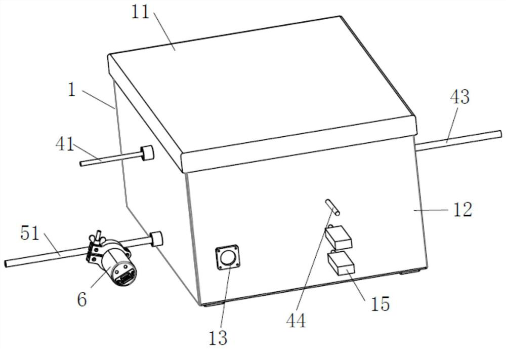
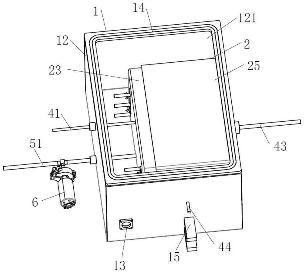
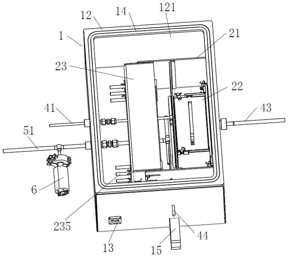
[0040] Such as Figure 1-9 As shown, a passivation equipment includes an isolation box 1 and a passivation box 2, the passivation box 2 is located inside the isolation box 1, and the passivation box 2 includes a loading structure 21, a carrier device 22, a spraying device and a heating device 23. The loading structure 21 carries the carrier device 22, the spray device and the heating device 23. The spray device is located between the carrier device 22 and the heating device 23. The spray device sprays oxygen or passivation gas, and the spray device sprays The passivating gas is in contact with the cross-sections of the sliced ​​cells.

[0041] In this embodiment, the passivation gas is set as a mixed gas containing ozone, and the description below refers to ozone. In addition, the sliced ​​battery 3 has at least one section.

[0042] The isolation box 1 is arranged as a square structure, and it includes an isolation body 12 and an isolation cover 11. The isolation body 12 inc...

Embodiment 2

[0059] Such as Figure 10 As shown, the difference between the present embodiment and the first embodiment is that in the first embodiment, ozone is introduced by the air duct 41 and sprayed through the spray pipe 42, while in the present embodiment, the oxygen is irradiated by the ultraviolet lamp 232 Ozone is produced.

[0060] In this embodiment, the ultraviolet lamp tube 232 is fixed on the housing 231 of the heating device 23, and the ultraviolet lamp tube 232 is provided with two groups. The tube 232 is located between the adjacent heating tubes 233. In the horizontal direction, the ultraviolet lamp tube 232 is located at the rear side of the heating tube 233, that is, the heating tube 233 is located between the ultraviolet lamp tube 232 and the carrier device 22. In order to prevent the heating tube 233 from For the radiation heating of the ultraviolet lamp tube 232, a heat insulating lampshade 234 is fixed between the two sets of fixing rods 235 of one group of heatin...


PUM


Abstract

The invention discloses passivation equipment which comprises an isolation box and a passivation box, the passivation box is located in the isolation box, the passivation box internally comprises a loading structure, a carrier device, a spraying device and a heating device, the loading structure bears the carrier device, the spraying device and the heating device, the spraying device is located between the carrier device and the heating device, and the heating device is located between the carrier device and the heating device. The spraying device sprays oxygen or passivating gas, the spraying device sprays the passivating gas to make contact with the section of the sliced battery, the technical scheme that the spraying device sprays ozone to the section of the sliced battery for passivating treatment is adopted, operation is easy, and industrial and large-scale development can be formed. The spraying pipe of the spraying device is used for spraying the passivation gas to the section of the sliced battery, so that the passivation gas is uniformly sprayed, and the passivation effect is ensured.

Description

technical field [0001] The invention belongs to the fields of semiconductor manufacturing and solar photovoltaic cell manufacturing, and in particular relates to a post-cutting process of photovoltaic cells. Background technique [0002] In recent years, photovoltaic technology has developed rapidly and has a wide range of applications. The market has shifted from focusing only on high power to the comprehensive requirements of high power, high power generation under any installation conditions, low attenuation and low cost, thereby further reducing the cost. The cost of electricity, so how to reduce the cost of electricity has become the core issue of the industry at present, and as the core component of photovoltaic system end power generation - photovoltaic modules are the top priority, high power modules are the most direct and most beneficial to promote "grid parity" As for the technology channel, the main ways to improve the module power are double-sided, half-cut, mul...

Claims


Application Information

Patent Timeline
Patent Type & Authority Applications(China)
IPC IPC(8): H01L31/18
CPCH01L31/1804H01L31/1868Y02P70/50
Inventor 林佳继庞爱锁刘群林依婷
Owner LAPLACE RENEWABLE ENERGY TECH CO LTD
Why Eureka
Try Eureka