
Charger protection circuit and method, charger, vehicle and storage medium

A technology for protecting circuits and chargers, which is applied to the protection circuits of chargers, chargers, vehicles and storage media, and can solve problems such as stoppage of on-board chargers, interruption of charging, failure to complete charging, etc.

Pending Publication Date: 2021-05-18
UNITED AUTOMOTIVE ELECTRONICS SYST
View PDF10 Cites 1 Cited by
  • Summary
  • Abstract
  • Description
  • Claims
  • Application Information

AI Technical Summary

Problems solved by technology

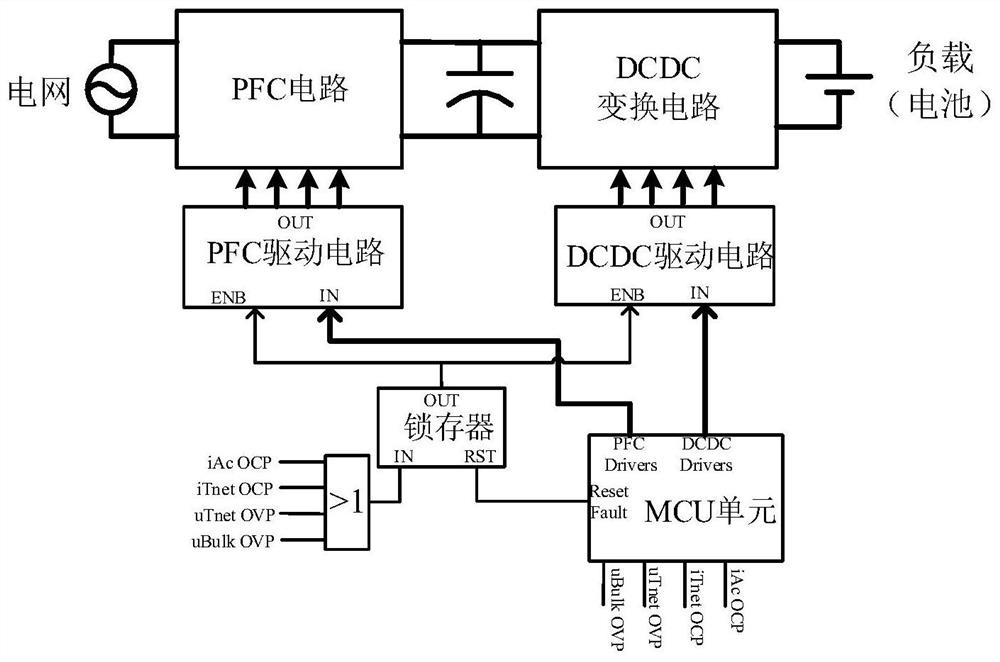
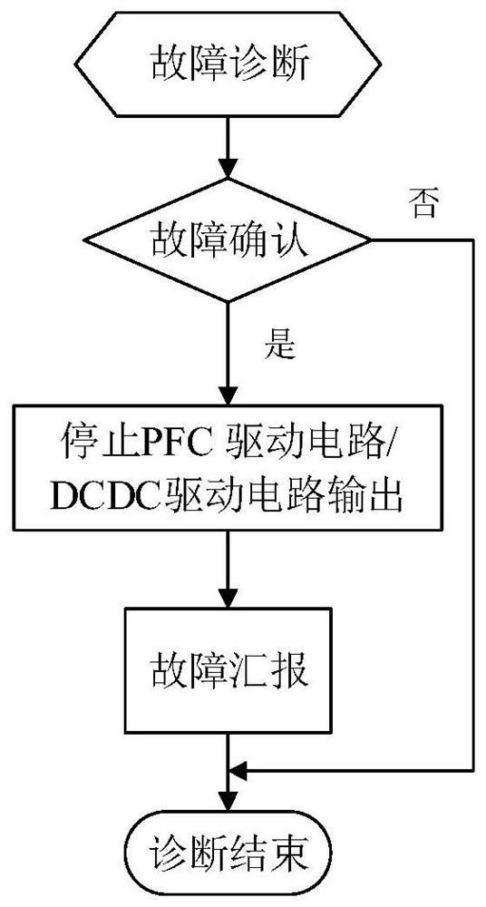
from figure 1 , figure 2 It can be seen that after the latch in the prior art receives the fault signal, it will block the PFC drive circuit and the DCDC drive circuit at the same time, and after the MCU detects the fault signal, it will stop the output of the PFC drive circuit and the DCDC drive circuit, and report the fault To the vehicle control system, eventually causing the on-board charger to stop working
[0004] When the input side of the charger is struck by lightning or a surge, although the traditional overcurrent protection circuit and overcurrent protection method can protect the PFC circuit, there is a charging interruption for such a short-term overcurrent fault. , which leads to serious defects such as low charging efficiency and even inability to complete charging

Method used


Image

  • Charger protection circuit and method, charger, vehicle and storage medium
  • Charger protection circuit and method, charger, vehicle and storage medium
  • Charger protection circuit and method, charger, vehicle and storage medium

Examples


Embodiment Construction

[0067] In order to make the purpose, advantages and features of the present invention more clear, the protection circuit, method, charger, vehicle and storage medium of the charger proposed by the present invention will be further described in detail below in conjunction with the accompanying drawings. It should be noted that all the drawings are in a very simplified form and use imprecise scales, and are only used to facilitate and clearly assist the purpose of illustrating the embodiments of the present invention. It should be understood that the drawings in the specification do not necessarily show the specific structure of the invention to scale, and that the illustrative features used to illustrate some principles of the invention in the drawings in the specification are also drawn in a somewhat simplified manner. The specific design features of the invention disclosed herein, including, for example, specific dimensions, orientations, locations and shapes will be determine...


PUM


Abstract

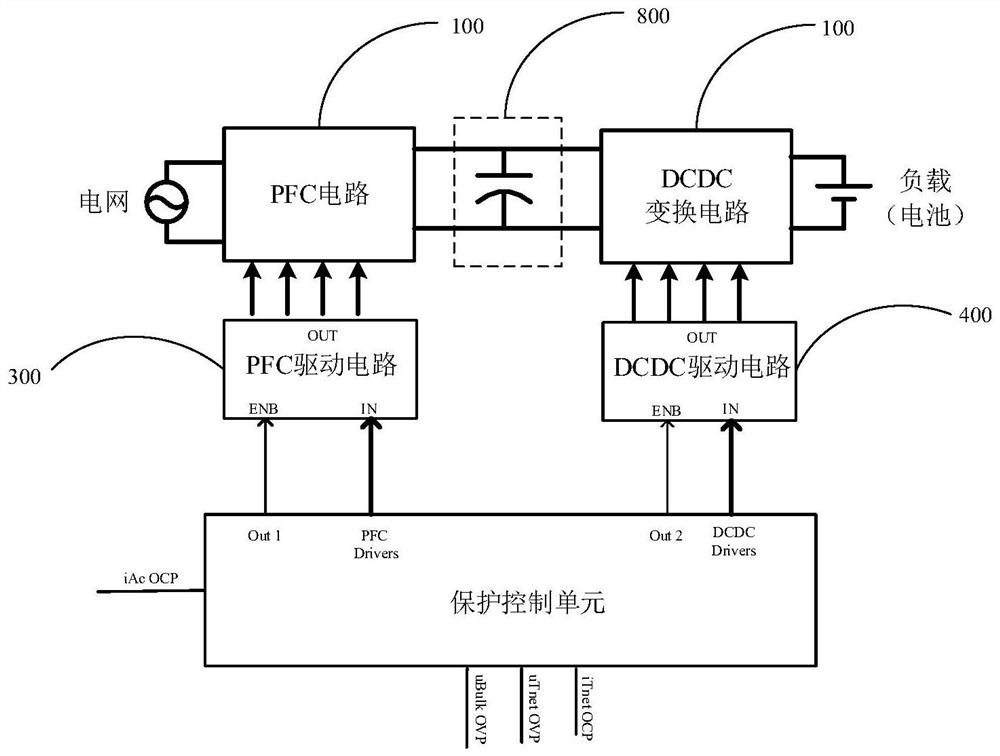
The invention provides a charger protection circuit and method, a charger, a vehicle and a storage medium. The protection circuit comprises a protection control unit, the charger comprises a PFC circuit, a DCDC conversion circuit, a capacitance circuit, a PFC drive circuit and a DCDC drive circuit which are electrically connected, and the protection circuit comprises a protection control unit. The protection control unit is connected with a fault signal, and the output end of the protection control unit is connected with the PFC drive circuit and the DCDC drive circuit. The protection control unit is configured to stop the output of the PFC drive circuit and control the DCDC drive circuit to drive the DCDC conversion circuit to continuously output if the input overcurrent is received; and and the protection control unit is also used for recovering the output of the PFC drive circuit according to a preset reset condition. According to the charger protection circuit and method, the charger, the vehicle and the storage medium provided by the invention, the charger does not stop working under a lightning surge working condition, and charging interruption or stop is avoided. And the robustness, the charging efficiency and the user experience of the charger are improved.

Description

technical field [0001] The invention relates to the technical field of circuit protection, in particular to a protection circuit of a charger, a method, a charger, a vehicle and a storage medium. Background technique [0002] When the on-board charger is connected to the power grid, certain harmonics will be generated to pollute the power grid, which will affect the working stability of electrical equipment. In order to limit the amount of harmonics, the on-board charger includes a PFC (Power Factor Correction, power factor correction) circuit in the front stage and a DCDC conversion circuit in the rear stage. PFC circuits usually use power switch tubes (such as IGBT, InsulatedGate Bipolar Transistor, insulated gate bipolar transistor), in order to protect the IGBT from being burned due to excessive current when the AC input side of the vehicle charger is subjected to lightning strikes or surge conditions , usually by detecting the input overcurrent to trigger the overcurre...

Claims


Application Information

Patent Timeline
IPC IPC(8): H02H9/02H02H7/20H02J7/00
CPCH02H9/02H02H7/205H02J7/00
Inventor 唐志俊李卓强张攀纪晓泳朱晓琪陈磊敏杨红
Owner UNITED AUTOMOTIVE ELECTRONICS SYST
Learn More