Permanent magnet type direct current motor driving device and electric equipment

A technology of DC motors and driving devices, applied in the direction of DC motor speed/torque control, conversion equipment without intermediate conversion to AC, output power conversion devices, etc., can solve the development constraints and influence of permanent magnet DC motors, and affect the economy Construction and national defense construction, difficult to deal with issues such as investigative technology

Inactive Publication Date: 2021-05-18
李静怡
View PDF0 Cites 0 Cited by
  • Summary
  • Abstract
  • Description
  • Claims
  • Application Information

AI Technical Summary

Problems solved by technology

At present, the traditional permanent magnet DC motors used in high-power national defense electric equipment have been difficult to cope with the increasingly advanced detection technology.
[0006] Based on the above reasons, the development of permanent magnet DC motors has been restricted and affected, which has affected economic construction and national defense construction.

Method used


Image

  • Permanent magnet type direct current motor driving device and electric equipment
  • Permanent magnet type direct current motor driving device and electric equipment
  • Permanent magnet type direct current motor driving device and electric equipment

Examples


Deformed example 1

[0095] In the example, Figure 4 can also be Figure 11 Instead, a new device is formed, and other structures and descriptions are the same.

[0096] In Modification 1, the same reference numerals are assigned to the same configurations as those in the first embodiment, and the same descriptions will be omitted.

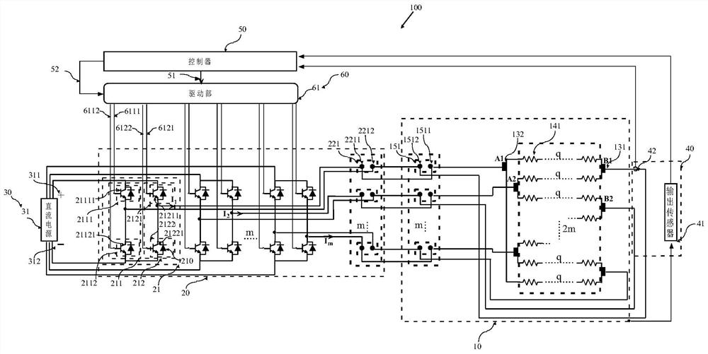
[0097] Figure 11 It is a schematic diagram of the circuit connection of the transverse section of the permanent magnet DC motor in Modification 11 of the present invention.

[0098] Such as Figure 11 As shown, the permanent magnet DC motor 10 in Modification 1 of the present invention also includes a field winding part 122, and the field winding part contains m field winding units, and m is an integer not less than 2. In this Modification 1, m is set to 3 .

[0099] The stator 12 includes three pairs of six main magnetic poles 121 and one field winding portion 122 . Each main magnetic pole 121 includes three excitation coils 12211, and each excitation coil 12...

Deformed example 2

[0106] In the example, Figure 4 can also be Figure 12 Instead, a new device is formed, and other structures and descriptions are the same.

[0107] In this modification 2, the same reference numerals are assigned to the same configurations as those in the first embodiment and the modification 1, and the same descriptions are omitted.

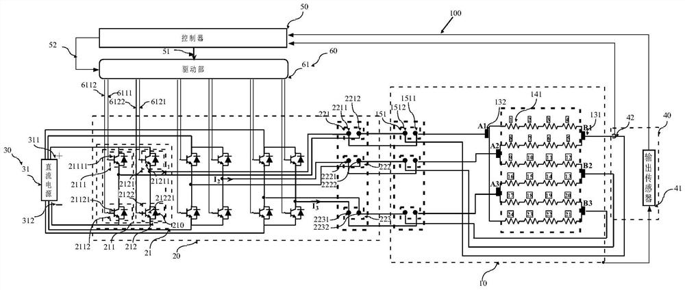
[0108] Figure 12 It is a schematic diagram of the circuit connection of the transverse section of the permanent magnet DC motor in Modification 2 of the present invention.

[0109] The field winding unit 122 includes m field winding units 1221 , and the m field winding units 1221 correspond to m pairs of main magnetic poles 121 respectively. Each excitation winding unit 1221 is formed by forming an excitation coil 12211 on a corresponding pair of main magnetic poles 121 with an insulated conductor strip made of a metal wire wrapped with an insulating layer.

[0110] Each pair of brushes 13 corresponds to the corresponding spatial position...

Deformed example 3

[0113] In the example, Figure 4 can also be Figure 13 Instead, a new device is formed, and other structures and descriptions are the same.

[0114] In the present modification 3, the same reference numerals are assigned to the same configurations as those in the first embodiment and the modification 1, and the same descriptions are omitted.

[0115] Figure 13 It is a schematic diagram of the circuit connection of the transverse section of the permanent magnet DC motor in Modification 3 of the present invention.

[0116] Such as Figure 13 As shown, the m one ends of the insulated conductor strips of all excitation winding units are electrically connected with the m N-pole corresponding brushes 132 in all brushes 13 to form m first terminals 1511, 1521 and 1531, and at the same time, all excitation windings The m other ends of the insulated conductor bar of the unit 1221 are electrically connected with the corresponding brushes 131 of m S poles in all brushes 13 to form ...


PUM


Abstract

The invention provides a permanent magnet type direct current motor driving device and electric equipment. The invention provides a permanent magnet type direct current motor driving device which comprises: a permanent magnet direct current motor. a DC power source; and a chopper which converts a constant voltage into a variable voltage based on a control signal, provides the variable voltage to the permanent magnet direct current motor and is provided with m chopping units, wherein each chopping unit comprises a first bridge arm, a second bridge arm, a first power supply output end and a second power supply output end, the first bridge arm comprises a first upper bridge arm and a first lower bridge arm which are connected in series, the second bridge arm comprises a second upper bridge arm and a second lower bridge arm which are connected in series, and the first bridge arm and the second bridge arm are connected in parallel. The control signals include m unit control signals respectively corresponding to the m chopping units and formed according to a predetermined phase shift rule, and each unit control signal includes four switching control signals corresponding to the corresponding chopping unit.

Description

technical field [0001] The invention belongs to the field of direct current motors, and in particular relates to a permanent magnet direct current motor driving device and electric equipment including the permanent magnet direct current motor driving device. Background technique [0002] The permanent magnet DC motor is a DC motor with a magnetic field composed of one or more permanent magnets. It has the advantages of small size, high efficiency, simple structure, and convenient speed regulation by changing the armature voltage. Therefore, it is widely used in automobiles and motorcycles. , electric bicycles, battery cars, ships and aviation industries. [0003] A DC motor is generally used together with a chopper to form a DC motor speed control device. In order to ensure system reliability, the maximum output current of the chopper is generally 2 to 3 times the rated current of the motor. High-power and high-performance DC motors, especially low-voltage and high-current ...

Claims


Application Information

Patent Timeline
Patent Type & Authority Applications(China)
IPC IPC(8): H02P7/293H02M3/10H02M3/158H02M1/14
CPCH02M1/14H02M3/10H02M3/1584H02P7/293
Inventor 李静怡
Owner 李静怡
Why Eureka
Try Eureka