A method and device used in a node for wireless communication

A node device and transmission node technology, applied in wireless communication, vehicle wireless communication service, transportation and packaging, etc., can solve problems such as TXUE conflict and loss, and achieve the effect of solving transmission delay and resource waste

Active Publication Date: 2022-06-17
SHANGHAI LANGBO COMM TECH CO LTD
View PDF14 Cites 0 Cited by
  • Summary
  • Abstract
  • Description
  • Claims
  • Application Information

AI Technical Summary

Problems solved by technology

For example, the PSFCH associated with the PSCCH / PSSCH of the 4 time slots is on the same symbol, when the TX UE sends data in any of the 4 time slots, and in the 4 time slots When receiving data on another time slot, the HARQ-ACK / NACK (Hybrid Automatic Repeat request-Acknowledge / NegativeAcknowlege, hybrid automatic repeat request-positive acknowledgment / negative acknowledgment) feedback for the two data packets is on the same symbol, Then this TXUE will generate a receiving / sending conflict, so that the HARQ-ACK / NACK feedback of a data packet has to be lost; or when two TXUEs send data to the same RX UE in these 4 time slots, for the two The HARQ-ACK / NACK feedback included in the data is also on the same symbol, so if the RX UE cannot send 2 PSFCHs at the same time, it must also lose a HARQ-ACK / NACK feedback

Method used


Image

  • A method and device used in a node for wireless communication
  • A method and device used in a node for wireless communication
  • A method and device used in a node for wireless communication

Examples


Embodiment 1

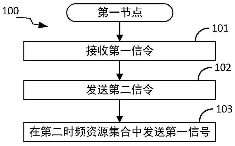
[0120] Embodiment 1 illustrates the processing flow chart of the first node of an embodiment of the present application, as shown in the appendix. figure 1 shown. in the attached figure 1 , each box represents a step. In Embodiment 1, the first node in this application first executes step 101 to receive the first signaling; then executes step 102 to send the second signaling; finally executes step 103 to send the first signal in the second time-frequency resource set a signal; the first signaling is used to determine a first identity and a first priority; the second signaling is used to indicate a second identity and a second priority; the second time-frequency resource set belongs to target resource sub-pool; the first signaling is used to determine a reference time-frequency resource set, the first time-frequency resource set is related to the reference time-frequency resource set, and the second signaling is used to indicate the first time-frequency resource set Two time...

Embodiment 2

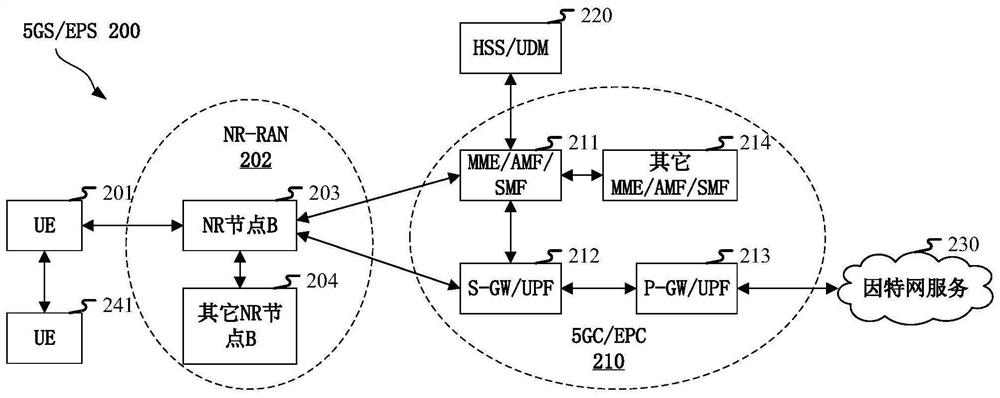
[0246] Embodiment 2 illustrates a schematic diagram of a network architecture according to the present application, as shown in the accompanying figure 2 shown.

[0247] attached figure 2 A diagram illustrating the network architecture 200 of the 5G NR, LTE (Long-Term Evolution) and LTE-A (Long-Term Evolution Advanced) systems. The 5G NR or LTE network architecture 200 may be referred to as 5GS (5G System) / EPS (Evolved Packet System) 200 by some other suitable term. The 5GS / EPS 200 may include one or more UE (User Equipment, User Equipment) 201, NG-RAN (Next Generation Radio Access Network) 202, 5GC (5G Core Network, 5G Core Network) / EPC (Evolved Packet Core, Evolved Packet Core) 210, HSS (Home Subscriber Server, Home Subscriber Server) / UDM (Unified Data Management) 220 and Internet Services 230. 5GS / EPS can be interconnected with other access networks, but not shown for simplicity these entities / interfaces. As shown, 5GS / EPS provides packet-switched services, however th...

Embodiment 3

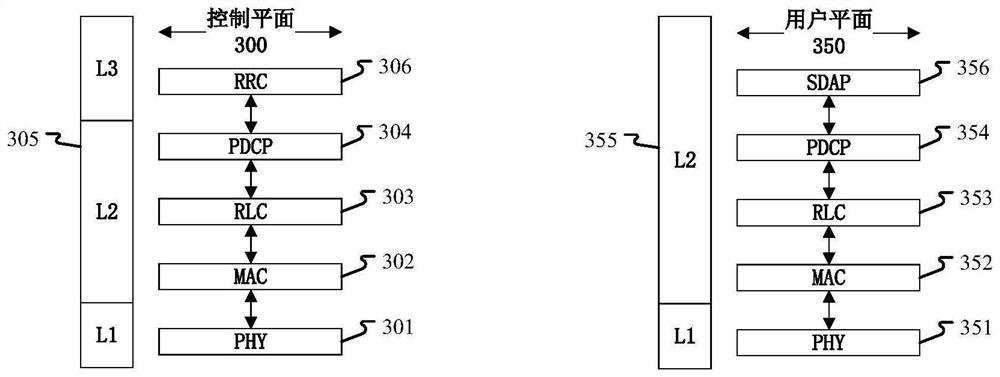
[0265] Embodiment 3 shows a schematic diagram of an embodiment of the radio protocol architecture of the user plane and the control plane according to the present application, as shown in the appendix. image 3 shown. image 3 is a schematic diagram illustrating an embodiment of a radio protocol architecture for the user plane 350 and the control plane 300, image 3 Exposing the control plane 300 with three layers for a first communication node device (UE, gNB or RSU in V2X) and a second communication node device (gNB, UE or RSU in V2X), or between two UEs Radio Protocol Architecture: Layer 1, Layer 2, and Layer 3. Layer 1 (L1 layer) is the lowest layer and implements various PHY (Physical Layer) signal processing functions. The L1 layer will be referred to herein as PHY301. Layer 2 (L2 layer) 305 is above the PHY 301 and is responsible for the link between the first communication node device and the second communication node device and the two UEs through the PHY 301 . The ...


PUM


Abstract

The present application discloses a method and an apparatus used in a node for wireless communication. The first node receives the first signaling; sends the second signaling; sends the first signal in the second time-frequency resource set; the second time-frequency resource set belongs to the target resource subpool; the first signaling is used For determining the first identity, the first priority and the reference time-frequency resource set; the first time-frequency resource set is related to the reference time-frequency resource set; the second signaling is used to indicate the second identity, the second priority level and the second time-frequency resource set; the relationship between the first transmission node device identified by the first identifier and the second transmission node device identified by the second identifier, the first priority and the The second priority is jointly used to determine whether the first time-frequency resource set belongs to the target resource subpool. This application effectively solves the problems of resource waste and transmission delay caused by PSFCH conflicts in the NR V2X system.

Description

technical field [0001] The present application relates to a transmission method and apparatus in a wireless communication system, and in particular, to a transmission scheme and apparatus related to a side link in wireless communication. Background technique [0002] The application scenarios of future wireless communication systems are becoming more and more diversified, and different application scenarios place different performance requirements on the system. In order to meet the different performance requirements of various application scenarios, at the 72nd plenary meeting of RAN (Radio Access Network, Radio Access Network) of 3GPP (3rd Generation Partner Project), it was decided that the new air interface technology (NR, New Radio ) (or Fifth Generation, 5G) to conduct research, passed the WI (WorkItem, work item) of NR at the 3GPPRAN#75 plenary meeting, and began to standardize NR. [0003] For the rapidly developing Vehicle-to-Everything (V2X) business, 3GPP has als...

Claims


Application Information

Patent Timeline
Patent Type & Authority Patents(China)
IPC IPC(8): H04L5/00H04L1/18H04W4/40H04W72/04H04W72/10
CPCH04L5/0055H04L5/0092H04L1/1812H04W4/40H04W72/20H04W72/56H04L1/18H04W72/04H04L5/0051Y02D30/70H04L5/0064
Inventor 刘瑾张晓博
Owner SHANGHAI LANGBO COMM TECH CO LTD
Why Eureka
Try Eureka