Femoral neck fracture angle stable type intramedullary fixing device

A femoral neck fracture and fixation device technology, which is applied in the field of medical equipment, can solve problems such as poor holding force of porotic bone, easy displacement of the nail body, and inability to withdraw the nail, so as to achieve enhanced anti-rotational stability, good mechanical properties, and reduced The effect of length

Inactive Publication Date: 2021-05-21
潘治军
View PDF0 Cites 3 Cited by
  • Summary
  • Abstract
  • Description
  • Claims
  • Application Information

AI Technical Summary

Problems solved by technology

The advantage of using three hollow threaded screws is that the nail body is thinner, less damage to the blood supply, less space for growth, less damage to the femur, and good pressure on the broken ends, which is conducive to healing; but The defect is that the nail body is fixed to the femoral neck through the greater trochanter, and the greater trochanter is mostly loose bone, and the femoral neck is also dominated by loose bone, and the holding force of loose bone is poor. Easy to shift, once the nail body is loosened and shifted, the broken end will grow slowly, and even cause nonunion or femoral head necrosis
[0003] The use of the main nail is generally used when the femoral shaft and the femoral neck are fractured at the same time. Because the femoral neck tensile locking nail has no compressive effect, it is rarely used for simple femoral neck fractures. The proximal femoral neck locking plate belongs to extramedullary fixation. System, the arm of force is longer, and the nail cannot be retracted, there is no follow-up pressure effect, and it is easy to fatigue

Method used


Image

  • Femoral neck fracture angle stable type intramedullary fixing device
  • Femoral neck fracture angle stable type intramedullary fixing device
  • Femoral neck fracture angle stable type intramedullary fixing device

Examples


Embodiment Construction

[0016] In order to facilitate the understanding of those skilled in the art, the embodiments of the present invention will be described in detail below in conjunction with the accompanying drawings.

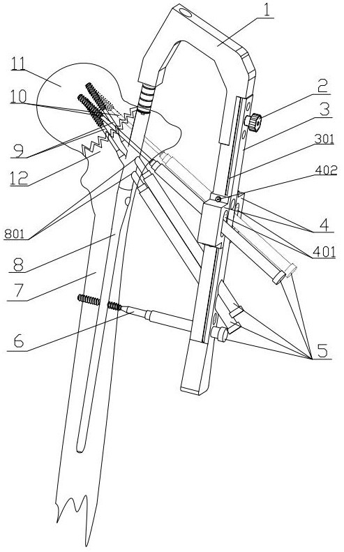
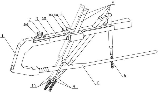
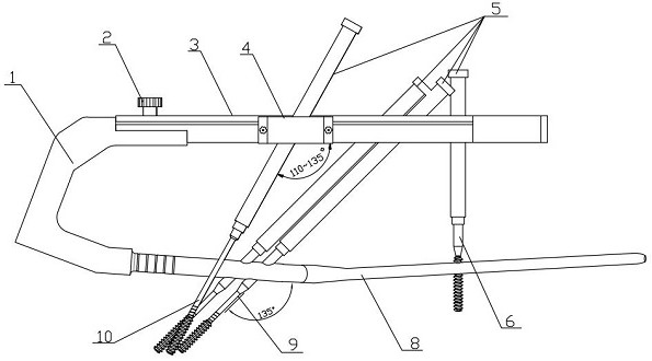
[0017] Depend on Figure 1-7 A femoral neck fracture angle-stabilized intramedullary fixation device shown includes an aimer A1, a fixing knob one 2, an aimer B3, an aimer attachment 4, a casing 5, a distal locking nail 6, a femoral shaft 7, a main Nail 8, tension lock nail 9, tension nail 10, femoral head 11, femoral neck 12; one end of the aimer A1 is tightly connected with the aimer B3 through the fixing knob 1, and the other end of the aimer A1 is connected with the main nail 8 through the thread connection; the two sides of the aiming device B3 are respectively provided with dovetail grooves 301, and the front and rear of the top are respectively provided with a first connection hole 302, a tension locking sleeve guide hole 303, and a distal locking nail sleeve guide hole 30...


PUM


Abstract

The invention discloses a femoral neck fracture angle stable type intramedullary fixing device. The device is structurally characterized in that one end of a sighting device A is connected with a sighting device B through a fixing knob I, and the other end of the sighting device A is connected with a main nail through threads; dovetail grooves are formed in the two side surfaces of the sighting device B, the sighting device B is connected with sighting device accessories through the dovetail grooves, tension lock pins and a far-end lock pin sleeve guide hole are arranged/formed at/in the top surface of the sighting device B, and a sleeve is inserted into the hole so that the tension lock pins and a far-end lock pin can be driven therein; each sighting device accessory consists of two symmetrical pieces, a pull nail sleeve guide hole penetrating up and down is formed in the top surface of each sighting device accessory so that pull nails except the main nail can be driven therein, and the optimal positions of the pull nails except the main nail can be selected through up-down sliding of the dovetail grooves; after femoral neck fracture is reduced and the main nail is inserted, the pull nails except the main nail are firstly driven in for pressurization, then two pull locking nails and a far-end locking nail are driven therein, and the three hollow nails for the femoral neck are dispersedly fixed, so that the anti-rotation capability is improved, and the stability of fracture reduction and healing is enhanced.

Description

technical field [0001] The invention belongs to the technical field of medical equipment, and in particular relates to a femoral neck angle-stabilizing fixed tension locking nail. Background technique [0002] With the aging of the society, the incidence of osteoporosis and the resulting femoral neck fractures is gradually increasing. Once the femoral neck fractures, most of the blood supply system of the femoral head is destroyed, and the mechanical length available for fixation is short. , relatively large shear force, difficult to effectively fix, prone to nonunion and femoral head necrosis. At present, the most commonly used internal fixation devices for the clinical treatment of femoral neck fractures are three hollow threaded screws, proximal femoral locking plates, and main nails. The advantage of using three hollow threaded screws is that the nail body is thinner, less damage to the blood supply, less growth space occupied, less damage to the femur, and good pressur...

Claims


Application Information

Patent Timeline
Patent Type & Authority Applications(China)
IPC IPC(8): A61B17/72A61B17/74A61B17/86A61B17/90
CPCA61B17/72A61B17/74A61B17/86A61B17/88
Inventor 潘静心潘治军
Owner 潘治军
Why Eureka
Try Eureka