Breathing exercise treatment device for chronic obstructive pulmonary disease
A treatment device and technology for chronic obstructive pulmonary disease, applied in nebulizers for treatment, other medical equipment, medicine equipment, etc., can solve the problems of inconvenient breathing for users, weak exercise effect of users, and insufficient atomization of medicinal liquid, etc. problem, achieve the effect of improving the efficiency of installation and replacement and convenient installation
- Summary
- Abstract
- Description
- Claims
- Application Information
AI Technical Summary
Problems solved by technology
Method used
Image
Examples
Embodiment 1
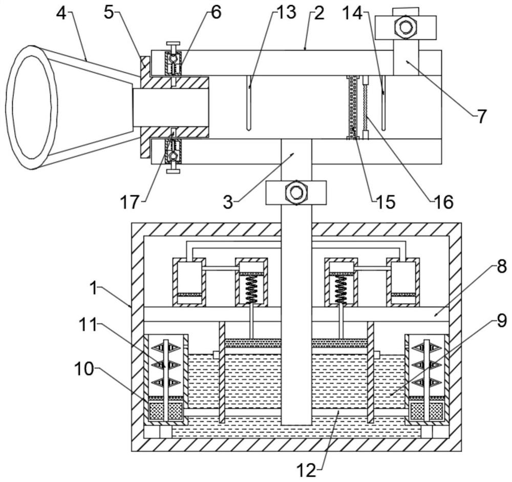
[0024] see figure 1 , in an embodiment of the present invention, a COPD respiratory exercise treatment device includes a box body 1 and a through tube 2, the box body 1 and the through tube 2 are communicated through an inhalation tube 3, and one side of the through tube 2 is installed There is a blowing nozzle 4, and the blowing nozzle 4 is fixedly connected with a mounting seat 5 near the end of the through pipe 2, and a fixing device 6 is arranged between the mounting seat 5 and the inner wall of the through pipe 2, and the other end of the through pipe 2 is connected above There is an exhalation pipe 7; the inhalation pipe 3 extends to the bottom of the box body 1, a partition 8 is arranged inside the box body 1, a liquid medicine pool 9 is arranged below the partition plate 8, and the liquid medicine pool 9 An atomization chamber 10 is arranged symmetrically on both sides, and an atomization device 11 is arranged inside the atomization chamber 10 , and the atomization cha...
Embodiment 2
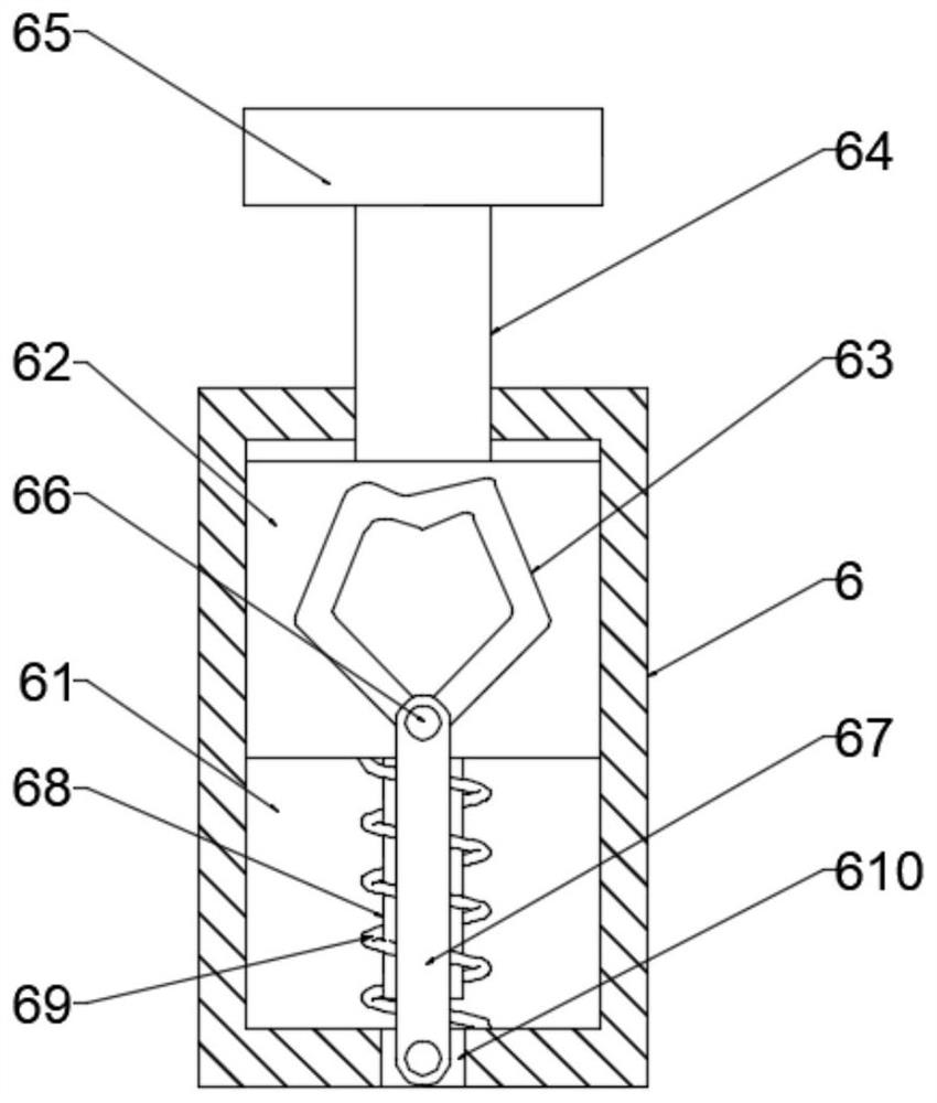
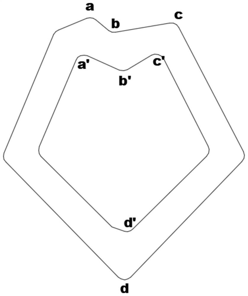
[0027] see figure 2 and 3 , in this embodiment, the fixing device 6 includes an installation cavity 61, a sliding seat 62 is slidably connected to the interior of the installation cavity 61, and a polygonal sliding groove 63 is provided on the surface of the sliding seat 62, and a sliding seat 62 is connected above the sliding seat 62. A transmission rod 64, the transmission rod 64 runs through the installation cavity 61 and is connected with a pressing plate 65, the inside of the polygonal chute 63 is slidably fitted with a sliding post 66, and a connecting rod 67 is hinged above the sliding post 66, and the connecting rod The other end of 67 is hingedly connected with the bottom of installation chamber 61, and the bottom of said slide seat 62 is fixedly connected with limit rod 68, and said limit rod 68 is provided with a compression spring 69 outside, and said mounting base 5 is symmetrically arranged with limit hole 17, the limit rod 68 is matched with the limit hole 17,...
Embodiment 3
[0030] see Figure 4 and 5 , in this embodiment, the atomization device 11 includes a rotating shaft 111, the rotating shaft 111 is connected to the bottom of the atomizing chamber 10 through a bearing, the lower part of the rotating shaft 111 is circumferentially equipped with fan blades 112, the A horizontal plate 113 is installed above the fan blades 112 in the atomizing chamber 10 , air holes are provided on the surface of the horizontal plate 113 , and a plurality of atomizing plates 114 are equidistantly arranged on the rotating shaft 111 above the horizontal plate 113 .
[0031] In this embodiment, the atomizing plate 114 is a diamond-shaped elastic plate, and a plurality of connecting springs 115 are installed inside the atomizing plate 114, and a liquid inlet 116 is installed on the top side of the atomizing chamber 10 to make the atomization When the plate 114 is rotated, the connecting spring 115 is stretched and contracted to increase the atomization effect of the...
PUM
 Abstract
Description
Claims
Application Information
 - R&D
- Intellectual Property
- Life Sciences
- Materials
- Tech Scout
- Unparalleled Data Quality
- Higher Quality Content
- 60% Fewer Hallucinations
Browse by: Latest US Patents, China's latest patents, Technical Efficacy Thesaurus, Application Domain, Technology Topic, Popular Technical Reports.
© 2025 PatSnap. All rights reserved.Legal|Privacy policy|Modern Slavery Act Transparency Statement|Sitemap|About US| Contact US: help@patsnap.com


