Active micro-fluidic chip
A chip, active technology, applied in the direction of material inspection products, measuring devices, instruments, etc., can solve the problems of increasing the difficulty of forming the chip body, the difficulty of assembly, and the high production cost, and achieve the effect of facilitating assembly, reducing resistance, and improving blood filtration efficiency.
- Summary
- Abstract
- Description
- Claims
- Application Information
AI Technical Summary
Problems solved by technology
Method used
Image

Examples
Embodiment 1
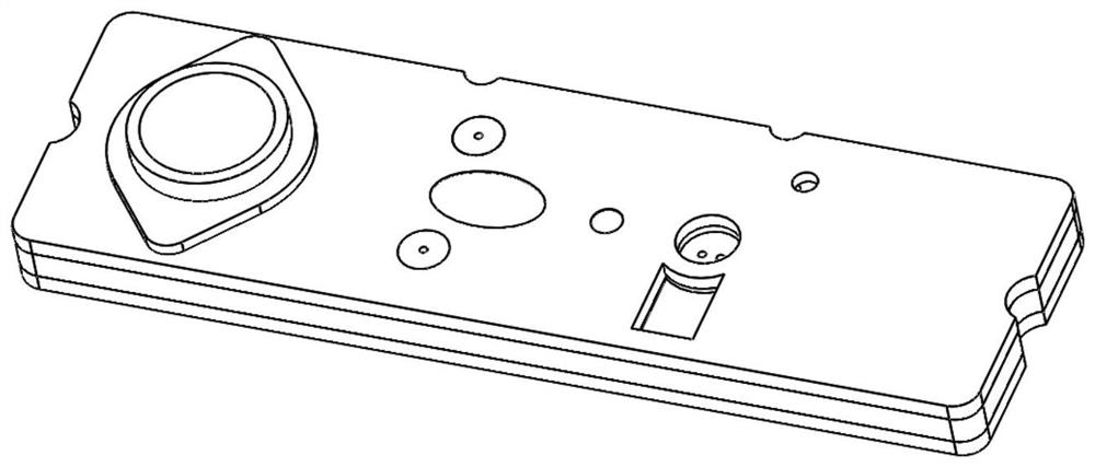
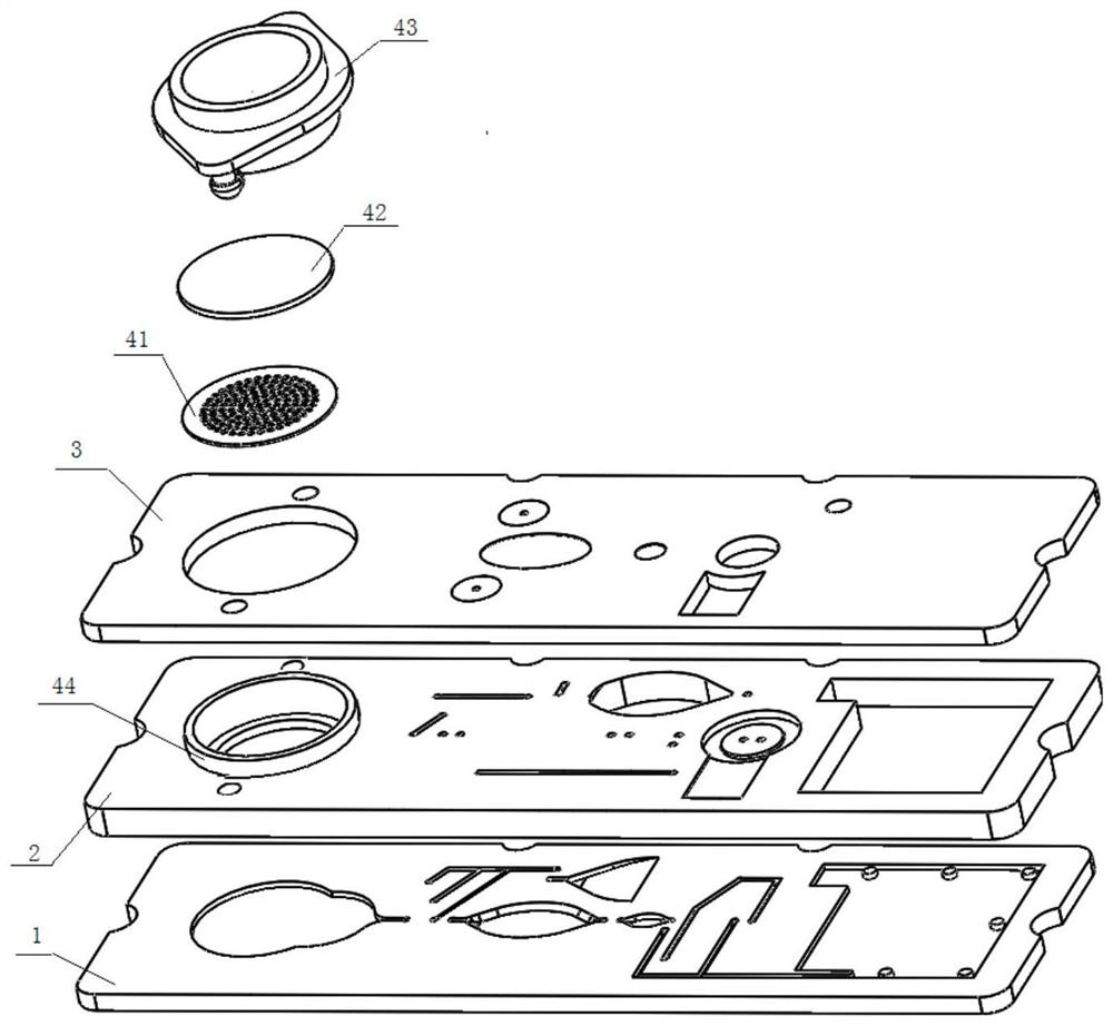
[0088] like Figures 1 to 7 As shown, the active microfluidic chip according to the present invention includes a chip body, the chip body is provided with a sample injection cavity, and the sample injection cavity is provided with a blood filtration module placement part, and the blood filtration module placement part is equipped with There is a blood filtration module; the blood filtration module includes a sample injection connection joint and a blood filtration assembly, and the sample injection connection joint is divided into a first clamping part 44 and a second clamping part 43 .
[0089] The first clip 44, such as figure 1 As shown, it is an annular member with a through hole in the middle, and a support structure is provided along the circumference of the inner wall of the through hole; the support structure is an annular boss provided along the circumference of the inner hole of the first clamping member 44 . In this embodiment, the first clip 44 is a cylindrical m...
Embodiment 2
[0112] like Figure 8 to Figure 11 As shown, most of the structures of this embodiment are the same as that of Embodiment 1, and the only difference is:
[0113]1. In this embodiment, the first clamping member 44 is directly supported by the blood filtration module placement part, and is clamped with the blood filtration module placement part when the connecting lug is engaged with the chip body. Specifically, in this embodiment, the through hole provided at the lower end of the first clamping member 44 abuts against the blood filtration module installation hole a provided on the middle chip 2, and the lower end of the first clamping member 44 extends outward. An annular flange is provided, and the annular flange is supported by the middle chip 2 outside the installation hole a of the blood filtration module, and the upper end of the first clip 44 is set through the installation hole b of the blood filtration module. In addition, in this embodiment, the clamping hole is provi...
Embodiment 3
[0118] like Figure 12-18 As shown, the active microfluidic chip disclosed in this embodiment is the same as most of the structures of the active microfluidic chip disclosed in Example 1, and the only difference is:
[0119] 1. In this embodiment, the cross-section of the sampling pool 1-1 arranged on the front of the lower chip is circular, and a collection flow channel 1-1-1 is set from the middle of the circular sampling pool to directly communicate with To the sample outlet of the sample pool 1-1, so as to communicate with the sample outlet channel of the sample pool 1-1-1.
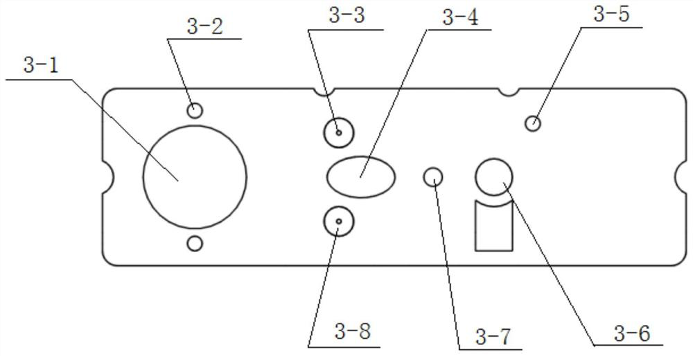
[0120] 2. In this embodiment, the diluent inlet 3-3 and the external gas outlet 3-8 set on the upper chip are all set as embedded structures, that is, the diluent inlet 3-3 and the external gas outlet 3- 8 are all set as embedded interfaces at the interface positions, and fluid through holes are provided on the bottom surface of the embedded interfaces to communicate with the corresponding internal f...
PUM
 Abstract
Description
Claims
Application Information
 - R&D Engineer
- R&D Manager
- IP Professional
- Industry Leading Data Capabilities
- Powerful AI technology
- Patent DNA Extraction
Browse by: Latest US Patents, China's latest patents, Technical Efficacy Thesaurus, Application Domain, Technology Topic.
© 2024 PatSnap. All rights reserved.Legal|Privacy policy|Modern Slavery Act Transparency Statement|Sitemap