Rotatable component of incineration hearth of cooking and heating furnace

A technology for heating stoves and hearths, which is applied in the direction of household stoves/stoves, climate sustainability, and combustion technology mitigation, etc. question

Active Publication Date: 2021-05-25
ZAOZHUANG FUYUAN ENVIRONMENTAL PROTECTION & ENERGY SAVING MACHINERY MFG CO LTD
View PDF7 Cites 0 Cited by
  • Summary
  • Abstract
  • Description
  • Claims
  • Application Information

AI Technical Summary

Problems solved by technology

The furnaces in the prior art are all equipped with refractory soil, and the flames of coal burning are connected to the refractory soil at the first time. The real heat is not accepted by the water in the furnace layer at the first time, but is absorbed by the refractory soil in the furnace. The gallbladder blocked it, and at this time the flame continued to rise. It should have directly burned the bottom of the pot or was drawn into the chimney by the draft effect of the chimney when it was supposed to burn the bottom of the pot. The pipes of the water pipes are baked by hot air, including the hot water in the interlayer of the furnace, which has little thermal effect. Objectively speaking, only 1 / 3 of the heat energy is used, that is to say, the fire is not burned directly, but is heated by the hot air effect generated by the fire. temperature transfer, this is the status quo

Method used


Image

  • Rotatable component of incineration hearth of cooking and heating furnace
  • Rotatable component of incineration hearth of cooking and heating furnace
  • Rotatable component of incineration hearth of cooking and heating furnace

Examples


Embodiment

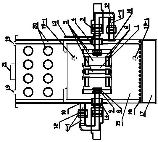
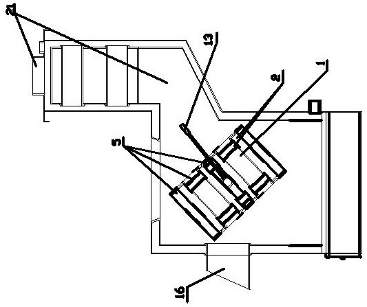
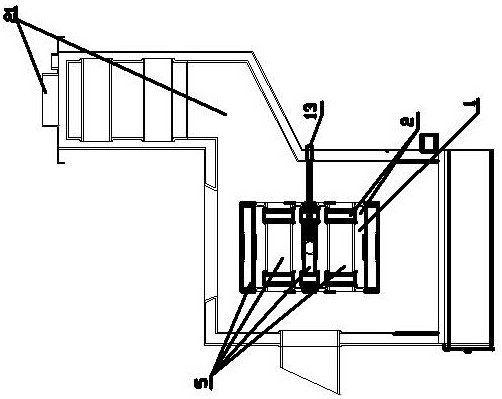
[0036] Embodiment: The structure of the rotary joint mainly includes a base, a rotating shaft, bearings assembled on the rotating shaft in sequence, a constant ring, a motion base, a slewing ring, an O-ring on the motion base, and a stopper The C-shaped buckle of the bearing and the slewing ring. The front and rear edges of the motion base are respectively provided with protrusions of different thicknesses. The protrusions respectively form the steps of the stop bearing and the constant ring. The rotary joint is assembled with the rotating shaft of each component. Inserted into the seat body, the assembly of the rotary joint is more convenient and fast, so as to reduce the operation cost. In addition, the shape of the shaft center portion of the swivel joint is formed such that the swivel joint swivel passage is arranged in the axial direction. The male thread portion is provided at the outer surface of the rotary shaft portion, and the female thread portion is provided at the...


PUM


Abstract

The invention discloses a rotatable component of an incineration hearth of a cooking and heating furnace. A rotary incineration hearth body is arranged in the hearth with an interlayer and a transverse water pipe, the incineration hearth body is provided with a multi-channel incineration pipe, and connecting threaded pipes connected with rotary joints are arranged at the two sides of the rotary incineration hearth body. The rotatable component of the incineration hearth of the cooking and heating furnace is characterized in that the rotary joints are arranged at the two ends of the incineration furnace body, a contact pressing force in the rotary joints enables a medium to circulate during sealing, the incineration furnace body rotates at any angle in the axial direction when incinerated, and the incineration furnace body is incinerated in fire all the time during rotating; and the appearance of the incineration hearth body is a cylinder, the interior of the incineration hearth body is the multi-channel incineration pipe with multiple pipes which communicate with the medium, and the multi-channel incineration pipe is a cylindrical multi-channel pipe which communicates with one another. The rotatable component of the incineration hearth of the cooking and heating furnace is high in heat exchange utilization rate, simple in structure, extremely low in failure rate and wide in application range, and the use cost, the manufacturing cost and the maintenance cost are reduced.

Description

technical field [0001] The invention relates to a stove for cooking, boiling water and heating. Background technique [0002] Since the heating furnace with an interlayer has a history of at least 40 years, the common sense of heating is to increase or decrease the diameter of the furnace according to the size of the indoor area, divided into 60, 80, 100, and 120. The larger the diameter of the furnace, the more The more radiators there are, of course, the more coal will be burned. To give just one example: a furnace with a diameter of 100 burns at least 100 kilograms of coal for 8 hours without a break. Based on the current average price of one yuan per kilogram, the heating fee for 8 hours is 100 yuan, and if it burns continuously for 24 hours, it will be a high 300 yuan. Why do you choose to use it with such a high cost? One word: cold! For example, in a 20-square-meter indoor space, a furnace without an interlayer is fired, and the diameter of the furnace is 60 mm. Com...

Claims


Application Information

Patent Timeline
Patent Type & Authority Applications(China)
IPC IPC(8): F24B1/183F24B1/191
CPCF24B1/183F24B1/191Y02E20/30
Inventor 孙有福陆国利胡晓曼
Owner ZAOZHUANG FUYUAN ENVIRONMENTAL PROTECTION & ENERGY SAVING MACHINERY MFG CO LTD
Why Eureka
Try Eureka