

Fiber bragg grating high-temperature strain gauge and calibration method thereof
A technology of high-temperature strain gauges and fiber gratings, which is applied in the direction of optical devices, instruments, and measuring devices, can solve problems such as the inability to realize structural synchronization measurement, and achieve the effects of avoiding chirp phenomenon, high measurement accuracy, and simple structure
- Summary
- Abstract
- Description
- Claims
- Application Information
AI Technical Summary
Problems solved by technology
Method used
Image

Examples
Embodiment 1
[0031]Example 1 Fiber Grating High Temperature Strap
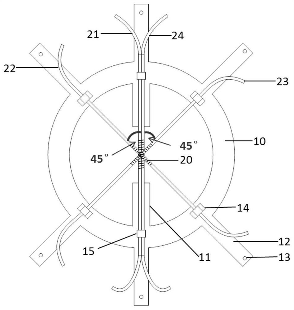
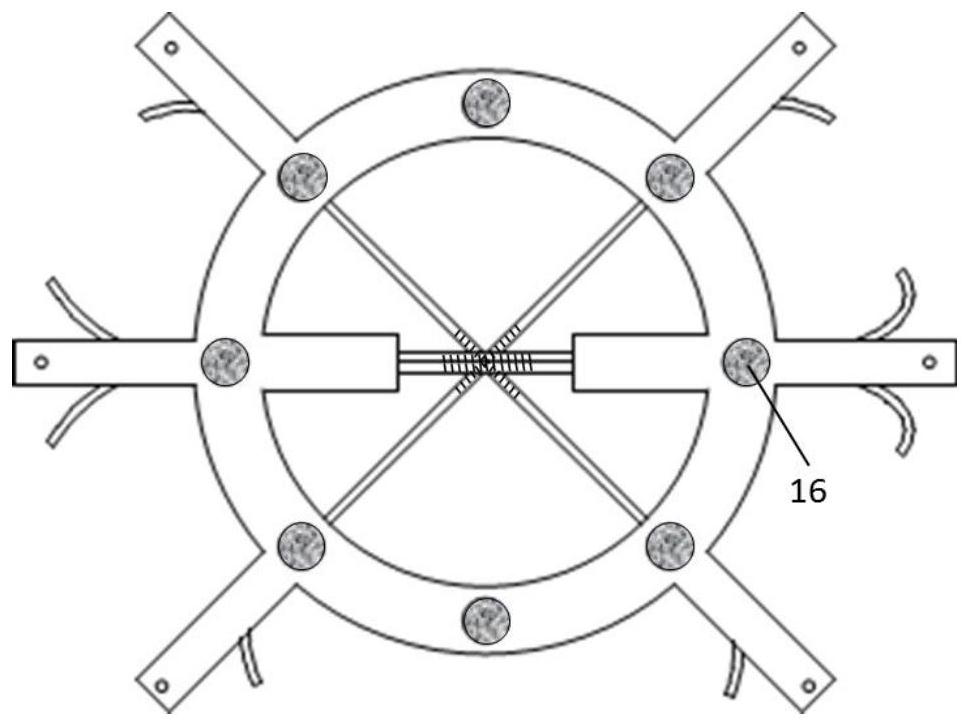
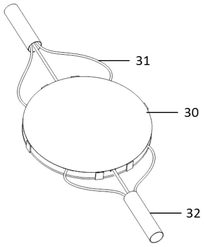
[0032]Refer to the attachmentimage 3The fiber grating high temperature strain piece of the present embodiment includes a circular annular sensor substrate 10, and the optical fiber mounting arm 11, optical fiber, and protective cover 30 on the sensor substrate 10, the fiber mount arm 11 along the sensor substrate 10 The inner circumference is extended, and the fiber is arranged in the diameter of the sensor substrate 10. The optical fiber mounting arm 11 is located in the same plane in the same plane with the sensor substrate 10. The size of the protective cover 30 matches the outer diameter of the sensor substrate 10, the edges of the shield 30 are uniformly distributed with the connecting portion, and the shroud 30 is connected to the sensor substrate 10 for protecting the optical fiber, the protective cover 30 is Metal Material.
[0033]The stiffness of the sensor substrate 10 is less than the stiffness of the structured structure,...
Embodiment 2
[0044]Example 2 Calibration Method
[0045]Based on the strain sheet in Example 1, the calibration method in this embodiment is performed in accordance with the following steps:
[0046]1) Two stretching devices corresponding to both ends of the first fiber are fixed to the stress sensor calibration platform by tensile bore;
[0047]2) Get the tensile shift to ΔL by tensile shift methodiWhen the wavelength drift amount Δλ of the first fiberiWhere i = 1, 2, 3, ..., n;
[0048]3) Measure the length L between the two fixed ends of the first fiber, calculate the strain ε in the first fiber direction.i= ΔLi / L (i = 1, 2, ..., n);
[0049]4) Several measuring points (Δλ)iΕi) Linear fitting, fitting slope K1That is, it is the strain sensitivity of the strain sheet in the first fiber direction;
[0050]5) Sequentially on the second fiber, the third optical fiber repeat steps 1) to 4), and the strain sensitivity K is obtained in the second fiber and the third optical fiber direction, respectively.2And K3The c...
PUM
| Property | Measurement | Unit |
|---|---|---|
| Outer diameter | aaaaa | aaaaa |
| Thickness | aaaaa | aaaaa |
Abstract
Description
Claims
Application Information