
Grounding knife-switch operating mechanism

A technology of grounding switch and operating mechanism, applied in grounding switches, contact operating parts, high-voltage air circuit breakers, etc., can solve problems such as inability to use robots, improve the success rate of alignment and process execution efficiency, and avoid jamming , the effect of concentric improvement

Pending Publication Date: 2021-05-25
YIJIAHE TECH CO LTD
View PDF9 Cites 0 Cited by
  • Summary
  • Abstract
  • Description
  • Claims
  • Application Information

AI Technical Summary

Problems solved by technology

This patent is a manually operated electric tool, which does not consider the opening of the pressure plate interlock, the insertion tolerance of the operating barrel, the insertion identification, the torsional position judgment of the grounding knife switch, etc., and cannot be applied to robots.

Method used


Image

  • Grounding knife-switch operating mechanism
  • Grounding knife-switch operating mechanism
  • Grounding knife-switch operating mechanism

Examples


Embodiment 1

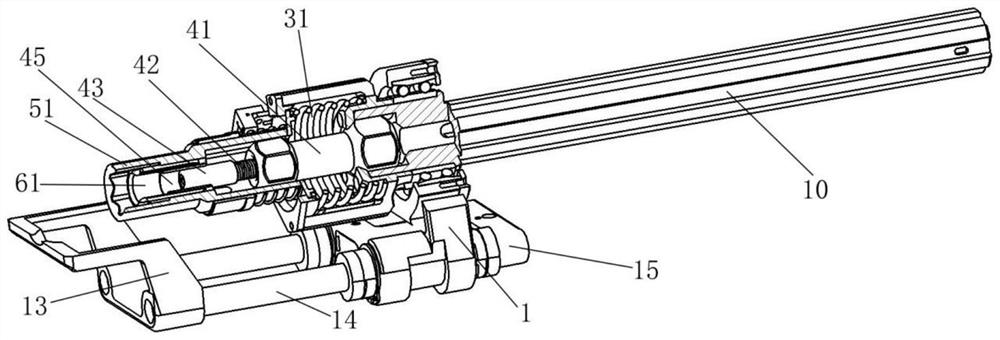
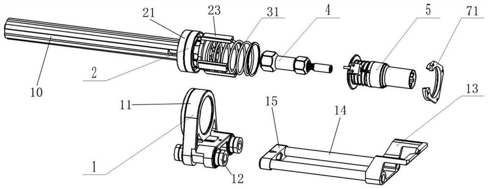
[0080] like figure 1 , 2 , 3, the grounding knife switch operating mechanism of this embodiment includes a telescopic pressure plate assembly 1, a mechanism bracket assembly 2, an adaptive assembly 3, a micro-view camera assembly 4, an operating head assembly 5 and an in-position detection assembly 6;

[0081] Among them, such as figure 2 , 3 As shown, the mechanism bracket assembly 2 includes a docking bracket (not shown in the figure) and a support rod 23, wherein the end surface of the docking bracket facing the grounding knife gate is provided with a hexagonal groove, and the other end surface of the docking bracket is docked with the robot transmission mechanism 10 through a flat key , and the telescopic and rotational degrees of freedom are provided by the robot-related transmission mechanism; at least three axially extending support rods 23 are evenly arranged in the circumferential direction of the end face of the docking bracket facing the grounding knife gate; in ...

Embodiment 2

[0098] like Figure 14 , 15 As shown, the grounding knife switch operating mechanism of this embodiment also includes a telescopic pressure plate assembly 1, a mechanism bracket assembly 2, an adaptive assembly 3, a micro-view camera assembly 4, an operation head assembly 5 and an in-position detection assembly 6, and wherein the telescopic pressure plate assembly 1 and the structure of the adaptive component 3 are the same as those of the first embodiment.

[0099] The mechanism bracket assembly 2 in this embodiment also includes a docking bracket, and the docking bracket is provided with a docking hole with a diameter larger than that of the robot transmission mechanism 10 passing through it; one end of the adaptive spring 31 of the adaptive assembly 3 is fixed by a spring spacer 32 Mounted on the docking bracket.

[0100] The micro-view camera assembly 4 of this embodiment also includes a fixing member 41 , a self-adjusting spring 42 , a camera rod 43 and a micro-view cam...


PUM


Abstract

The invention discloses a grounding knife-switch operating mechanism, which comprises a butt joint bracket; a telescopic pressing plate assembly rotatably installed on the butt joint support through a bearing, wherein a telescopic pressing plate used for pressing a cabinet grounding knife interlocking pressing plate downwards is installed on the telescopic pressing plate assembly; an operation head assembly in butt joint with a robot transmission mechanism, wherein the robot related transmission mechanism provides stretching and rotation freedom degrees; a butt joint groove matched with the grounding knife-switch operating rod is formed in the front end of the grounding knife-switch operating rod and is used for grounding knife-switch operation; the operation head assembly and the butt joint support are connected in a matched mode through a self-adaption assembly, and self-adaption positioning of the operation head assembly is achieved through the self-adaption assembly. According to the operation mechanism, five-degree-of-freedom passive self-adaption is achieved through the single-stage or double-stage internal and external hexagonal gap butt joint characteristic, large-torque transmission is achieved directly through the hexagonal connecting rods, the self-adaption capacity is high, and the structure is simple.

Description

technical field [0001] The invention relates to the field of mechanical structures, in particular to a grounding knife switch operating mechanism. Background technique [0002] Switching operation is an operation that changes the operating state of power grid equipment, and is an indispensable part of the power system. The operation of the grounding switch is a key step in switching the cabinet between standby and maintenance states. The operation of the 10kv switch cabinet grounding knife switch has difficulties such as small operating space, large operating torque, and the cabinet mechanism jamming robot is difficult to judge that the operation is in place. At the same time, there is a cabinet ground knife interlock plate pressure outside the ground knife switch operation hole of the switch cabinet. During the manual operation, both hands need to cooperate to complete the pressure plate depression and the insertion of the manual operating rod. [0003] The present invent...

Claims


Application Information

Patent Timeline
Patent Type & Authority Applications(China)
IPC IPC(8): H01H31/02H01H31/00H01H3/02
CPCH01H31/02H01H31/003H01H3/02
Inventor 程敏蔡海晨刘静郭强李剑涛
Owner YIJIAHE TECH CO LTD
Learn More