Heat exchange humidifying device for fuel cell

A fuel cell and humidification device technology, applied in the direction of fuel cells, circuits, electrical components, etc., can solve the problems of unfavorable system integration, increased component volume, waste of integration space, etc., to achieve increased purge ports, multiple functions, and reduced pipelines the effect of using

Pending Publication Date: 2021-05-25
HAIDRIVER (QINGDAO) ENERGY TECH CO LTD
View PDF0 Cites 0 Cited by
  • Summary
  • Abstract
  • Description
  • Claims
  • Application Information

AI Technical Summary

Problems solved by technology

[0003] In the prior art, the fuel cell system needs to cool and humidify the air during the reaction process. According to the prior art, the intercooler is used to solve the cooling problem, and the humidifier is used to solve the humidification problem. To connect, the volume is large and there are many pipelines,

Method used


Image

  • Heat exchange humidifying device for fuel cell
  • Heat exchange humidifying device for fuel cell
  • Heat exchange humidifying device for fuel cell

Examples


Embodiment Construction

[0018] The following will clearly and completely describe the technical solutions in the embodiments of the present invention in conjunction with the accompanying drawings in the embodiments of the present invention. Obviously, the described embodiments are only some of the embodiments of the present invention, not all of them. Based on the embodiments of the present invention, all other embodiments obtained by persons of ordinary skill in the art without making creative efforts belong to the protection scope of the present invention.

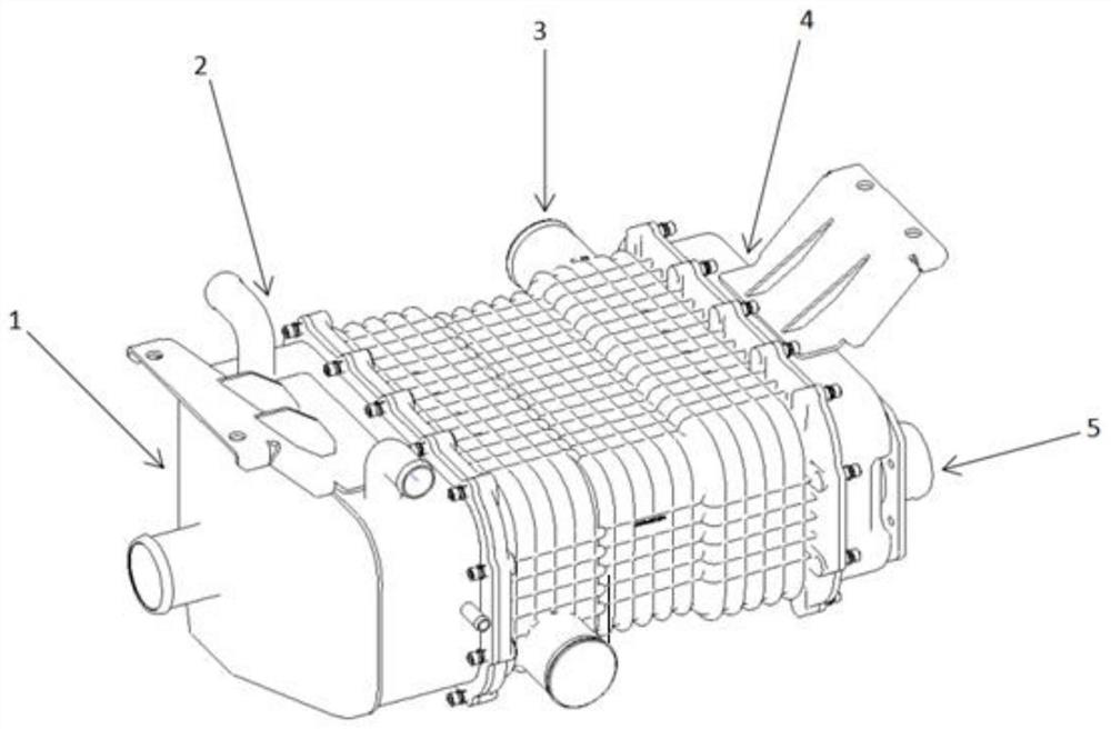
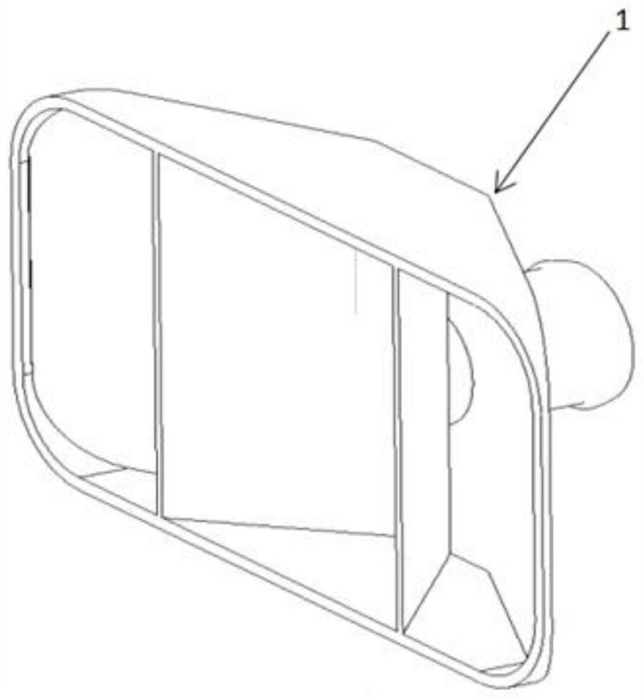
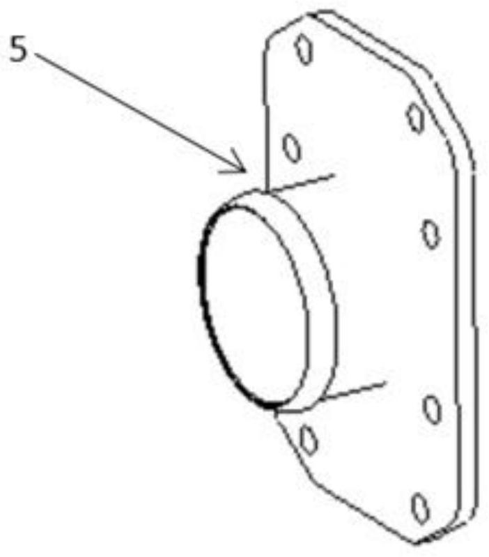
[0019] see Figure 1 to Figure 3 , the present invention provides a technical solution: a heat exchange and humidification device for a fuel cell, the intercooler inlet cavity 1 and the intercooler main body 2 are connected together by welding, the intercooler inlet cavity 1 ensures that the air compressor The incoming gas can evenly enter the main body of the intercooler 2. In addition to cooling the air, the main body of the intercooler 2 als...


PUM


Abstract

The invention relates to the technical field of fuel cells, in particular to a heat exchange humidifying device for a fuel cell, which comprises an intercooler inlet cavity, an intercooler main body is arranged on the top surface of the intercooler inlet cavity, a humidifier main body is arranged on the surface of the intercooler main body, a gas mixing cavity is arranged on the surface of the humidifier main body, and an adapter is arranged on the surface of the gas mixing cavity. The heat exchange humidifying device has the beneficial effects that the heat exchange humidifying device for the fuel cell is small in size and high in integration level; and, through simulation design, the welding angle of the baffle is changed, under the condition that the length of an inlet pipeline of the intercooler is not increased, the uniformity of gas distribution is guaranteed, the intercooler, the humidifier and a throttle valve (or a tee joint) can be integrated at the same time, and the use of pipelines is reduced.

Description

technical field [0001] The invention relates to the technical field of fuel cells, in particular to a heat exchange and humidification device for fuel cells. Background technique [0002] Fuel cell system refers to the power generation system with fuel cell as the core, fuel supply and circulation system, oxidant supply system, water / heat management system, control system, etc.; a single fuel cell stack cannot be used for power generation, it must be The fuel cell power generation system is composed of fuel supply and circulation system, oxidant supply system, water / heat management system, and control system to output power externally. [0003] In the prior art, the fuel cell system needs to cool and humidify the air during the reaction process. According to the prior art, the intercooler is used to solve the cooling problem, and the humidifier is used to solve the humidification problem. To connect, the volume is large and there are many pipelines, which is not conducive t...

Claims


Application Information

Patent Timeline
IPC IPC(8): H01M8/04029H01M8/04119
CPCH01M8/04029H01M8/04126Y02E60/50
Inventor 谢佳平朱维
Owner HAIDRIVER (QINGDAO) ENERGY TECH CO LTD
Why Eureka
Try Eureka