Water purifier and method for protecting water pump by using water purifier

A water purifier and water pump technology, applied in chemical instruments and methods, separation methods, osmotic/dialysis water/sewage treatment, etc., can solve the problems of no idling protection of water pumps, harsh noises, etc., to prevent waterless idling and burning. Effect

Active Publication Date: 2021-05-28
SHENZHEN ROMER ENVIRONMENTAL ENG CO LTD
View PDF12 Cites 1 Cited by
  • Summary
  • Abstract
  • Description
  • Claims
  • Application Information

AI Technical Summary

Problems solved by technology

[0005] The purpose of the present invention is to provide a water purifier that solves the problem of harsh noise caused by a large amount of air in the water purifier pipeline without idling protection for the water pump. Another object of the invention is to provide a method of protecting the water pump of the water purifier by discharging air bubbles

Method used


Image

  • Water purifier and method for protecting water pump by using water purifier
  • Water purifier and method for protecting water pump by using water purifier
  • Water purifier and method for protecting water pump by using water purifier

Examples


Embodiment 1

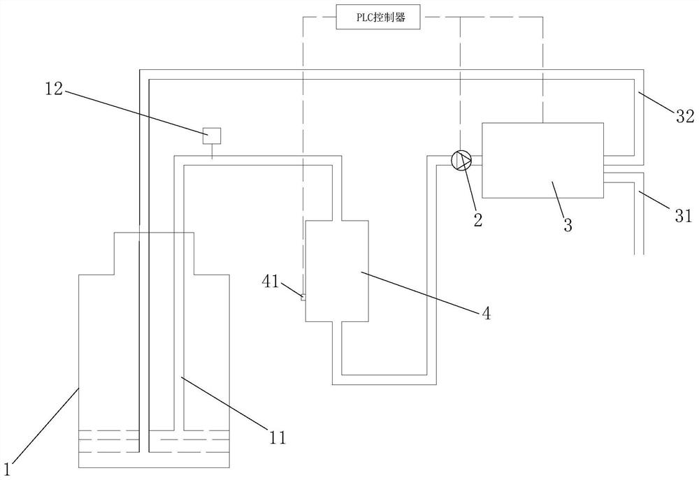
[0044] see figure 2 As shown, in order to solve the defects existing in the prior art, the present invention provides a water purifier, including a raw water bucket 1, a water pump 2, a filtration system 3 and a control assembly, and the raw water pipe 11 is equipped with a gas-water liquid The level control tank 4, the water pump 2 extracts the raw water in the raw water bucket 1 and collects it into the air-water level control tank 4, and then flows to the filter system 3 to filter, and the purified water is discharged through the clean water pipe 31, and the concentrated water is discharged through the return The water pipe 32 flows back to the raw water barrel 1, and a water level switch 41 is arranged on the outer wall of the tank 4 of the air-water level control tank 4. The control component is a PLC controller, and the PLC controller is respectively connected with the induction switch, the Said water pump 2, said filtering system 3 are controlled and connected;

[004...

Embodiment 2

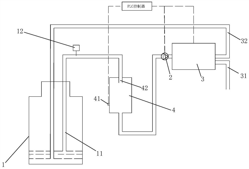
[0053] see image 3 As shown, the difference between this embodiment and Embodiment 1 is that the water inlet of the gas-water level control tank 4 extends to the inner cavity of the tank to form a water inlet pipe 42, and the raw water enters the gas-water level control tank 4 through the water inlet pipe 42. The inner cavity of the tube 4 allows the raw water to drop directly from the inlet pipe and splash on the liquid surface, so that the air in the tank is converted into small air bubbles and then mixed with the raw water to prevent the raw water from flowing down slowly along the inner wall of the tank. The pump 2 will The raw water mixed with small air bubbles is pumped to the filter system 3 for filtration.

Embodiment 3

[0055] see Figure 4 As shown, the difference between this embodiment and Embodiment 1 is that the water outlet of the air-water level control pipe 4 extends toward the inner cavity of the tank to form an outlet pipe 43, which is located at the end of the outlet pipe 43 in the inner cavity of the tank. The first water outlet 431 and the second water outlet 432 are respectively pierced on the water outlet pipe 43, and the water level switch 41 is located between the first water outlet 431 and the second water outlet 432;

[0056] The cross-sectional area of ​​the first water outlet 431 and the second water outlet 432 are the same, the sum of the cross-sectional areas of the two water outlets is equal to the cross-sectional area of ​​the water outlet pipe 43, and the cross-sectional area of ​​a single water outlet is half of the cross-sectional area of ​​the water outlet pipe.


PUM


Abstract

The invention relates to a water purifier and a method for protecting a water pump by using the water purifier. The water purifier comprises a raw water barrel, a water suction pump, a filtering system and a control assembly, wherein a gas-water liquid level control tank is installed on a raw water pipe, raw water in the raw water barrel is sucked by the water suction pump and collected to the gas-water liquid level control tank, and then flows to the filtering system to be filtered to generate purified water, the generated purified water is discharged through a purified water pipe, the generated concentrated water flows back to the raw water barrel through a water return pipe, an inductive switch is arranged on the outer wall of the tank body of the gas-water liquid level control tank, and the control assembly is in control connection with the inductive switch, the water suction pump and the filtering system. The water purifier is matched with the water pump protection method, the gas-water liquid level control tank is utilized for collection and transfer, the water pump and the filtering system are protected by discharging bubbles, the service life of the water pump is prolonged, and the filtering system is prevented from making harsh noise and violent vibration during working.

Description

technical field [0001] The invention relates to the technical field of water purifiers, in particular to a water purifier and a method for the water purifier to protect a water pump and a filter system by discharging air bubbles. Background technique [0002] A pump is a machine that transports or pressurizes a liquid. It transmits the mechanical energy of the prime mover or other external energy to the liquid to increase the energy of the liquid. It is mainly used to transport liquids including water, oil, acid and alkali, emulsions, and suspoemulsions. It can also transport liquid, gas mixture and liquid containing suspended solids. The technical parameters of pump performance include flow rate, suction lift, lift, shaft power, water power, efficiency, etc.; according to different working principles, it can be divided into Positive displacement pump, vane pump and other types. [0003] The water pumps currently used in tea bar machines or filtering devices, when the raw w...

Claims


Application Information

Patent Timeline
Patent Type & Authority Applications(China)
IPC IPC(8): B01D35/02C02F1/44G01D21/02
CPCB01D35/02C02F1/44G01D21/02
Inventor 王桂林郭喜旗邓春凤覃积林陈武装
Owner SHENZHEN ROMER ENVIRONMENTAL ENG CO LTD
Why Eureka
Try Eureka