Three-dimensional vibration-assisted milling processing system and three-dimensional vibration-assisted milling method for structural surface

A three-dimensional vibration and milling processing technology, which is applied in the direction of metal processing equipment, milling machine equipment, manufacturing tools, etc., can solve the problem that the processing accuracy and processing efficiency of structural surface are difficult to improve at the same time, and achieve the reduction of crack propagation, small processing force, and smooth surface. The effect of high integrity

Active Publication Date: 2022-07-12
广东致志精密塑胶模具有限公司
View PDF12 Cites 0 Cited by
  • Summary
  • Abstract
  • Description
  • Claims
  • Application Information

AI Technical Summary

Problems solved by technology

[0004] The purpose of the present invention is to provide a three-dimensional vibration-assisted milling processing system for the problem that the structural surface processing accuracy and processing efficiency in the prior art are difficult to improve at the same time

Method used


Image

  • Three-dimensional vibration-assisted milling processing system and three-dimensional vibration-assisted milling method for structural surface
  • Three-dimensional vibration-assisted milling processing system and three-dimensional vibration-assisted milling method for structural surface
  • Three-dimensional vibration-assisted milling processing system and three-dimensional vibration-assisted milling method for structural surface

Examples


Embodiment 1

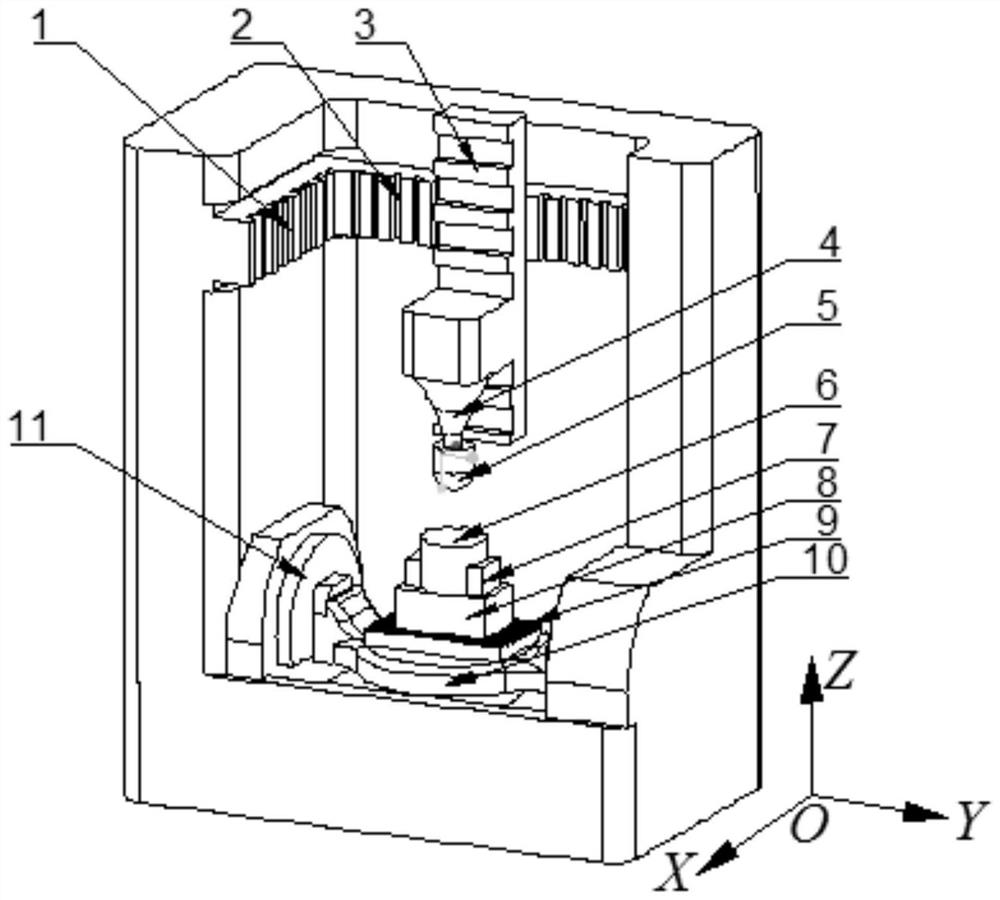
[0056] Three-dimensional vibration-assisted milling processing systems, including CNC machine tools and three-dimensional vibration-assisted devices8, such as figure 1 As shown, the CNC machine tool includes an X-direction slide rail 1, a Y-direction slide rail 2 and a Z-direction slide rail 3 at the top, and a Z-direction shaft 10 and a Y-direction shaft 11 at the bottom, wherein:

[0057] The X-direction slide rail 1 and the Y-direction slide rail 2 are perpendicular to each other, and the Z-direction slide rail 3 is driven to move horizontally along the X-direction slide rail 1 in the X-axis direction, and along the Y-direction slide rail 2 Move horizontally in the Y-axis direction, the processing assembly is driven to move horizontally along the Z-direction slide rail 3 in the Z-axis direction, and the processing assembly includes a driving mechanism, a main shaft 4 driven to rotate by the driving mechanism, and a Tool 5 on spindle 4;

[0058] The workpiece 6 is fixed on ...

Embodiment 2

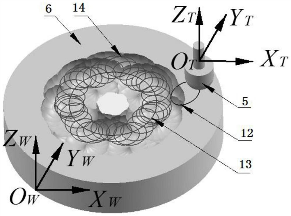
[0062] In the three-dimensional vibration-assisted milling processing system of Embodiment 1, a coordinate system is established. There are three coordinate systems: machining system coordinate system, workpiece coordinate system and tool coordinate system.

[0063] (1) Coordinate system of processing system:

[0064]The coordinate system of the processing system is represented by O-XYZ, which is based on the center of the machine tool table as the origin, the X axis is parallel to the X-direction slide rail of the machine tool, the Y axis is parallel to the machine tool Y-direction slide rail, and the Z axis is parallel to the machine tool Z-direction slide rail.

[0065] (2) Workpiece coordinate system:

[0066] O for workpiece coordinate system W -X W Y W Z W Indicates that the origin is located at a certain point of the workpiece, X W axis, Y W axis, Z W The axes are all parallel to the X, Y, and Z axes in the machining system coordinate system.

[0067] (3) Tool ...

Embodiment 3

[0070] A three-dimensional vibration-assisted milling method for a structural surface, comprising the following steps:

[0071] Define the tool coordinate system as O T -X T Y T Z T , define the workpiece coordinate system as O W -X W X W Z W .

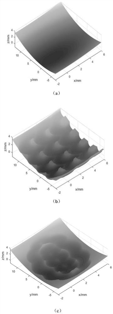
[0072] Step 1, in the tool coordinate system, the surface topography equation of the modeling tool is:

[0073]

[0074] In the formula (1), the x T , y T ,z T is the coordinate of any point on the tool surface in the tool coordinate system, denoted as C T Point coordinates, R is the tool surface C T The distance from the point to the tool axis, θ is O T C T in X T O T Y T Surface projection and X T The angle of the axis.

[0075] In the formula (1), when the tool shape is spherical with radius r, R takes the value rsinφ, where The value of r is 1 during simulation.

[0076] Step 2, in the workpiece coordinate system, establish the surface topography equation of the workpiece as:

[0077] F(x w , y w ,z ...


PUM


Abstract

The invention discloses a three-dimensional vibration-assisted milling method for a structured surface, comprising the following steps: establishing a mathematical model of the surface topography of a tool and a workpiece, setting a three-dimensional vibration device and a running path of a numerically controlled machine tool, calculating the tool and the workpiece each time in the processing process The position and attitude relationship at a moment, the structure morphology after vibration-assisted milling is obtained by comparative analysis. The vibration-assisted milling method proposed by the present invention can realize the preparation of micro-structures on various complex free-form surfaces in combination with the characteristics of high degree of freedom of numerical control milling, rich types of machined surfaces, wide operating frequency range of the vibration device, and high running accuracy. surface.

Description

technical field [0001] The invention relates to the technical field of structural surface processing, in particular to a three-dimensional vibration-assisted milling processing system and a three-dimensional vibration-assisted milling method of a structural surface Background technique [0002] In nature, many biological surfaces are uniformly arranged with some periodic microstructures, which make their biological surfaces exhibit a variety of properties. The application of shark skin surface drag reduction structure can solve problems such as aircraft thermal shock and high-speed rail speed increase. The application of the hydrophobic structure on the surface of the lotus leaf can solve the problem of anti-fouling on the bottom of the ship. The wonderful functions brought about by the tiny structures on the surface of these substances are pushing my country's aerospace and defense industry into a new era. [0003] With the research of structural surface processing techno...

Claims


Application Information

Patent Timeline
Patent Type & Authority Patents(China)
IPC IPC(8): B23C3/00
CPCB23C3/00Y02T70/10
Inventor 王桂莲刘文瑞吕秉锐冯志坚闫世程刘利周海波
Owner 广东致志精密塑胶模具有限公司
Why Eureka
Try Eureka