Industrial robot step-by-step calibration system and method

An industrial robot and calibration system technology, applied in the field of industrial robot step-by-step calibration system and robot calibration, can solve the problem that the accurate position of the robot base coordinate system cannot be calibrated, the robot base coordinate system cannot be accurately calibrated, and it is difficult to ensure the reliability of the calibration results. and other problems, to achieve the effect of large measurement range, reduced accuracy requirements, and convenient operation

Pending Publication Date: 2021-05-28
NINGBO INST OF MATERIALS TECH & ENG CHINESE ACADEMY OF SCI
View PDF6 Cites 9 Cited by
  • Summary
  • Abstract
  • Description
  • Claims
  • Application Information

AI Technical Summary

Problems solved by technology

However, most of the existing new robot calibration methods are aimed at the calibration of the kinematic parameters of the robot body, so it is impossible to accurately calibrate the robot base coordinate system; some of the new calibration methods that can realize the calibration of the robot base coordinate system, the calibration device can only collect robot Therefore, it is difficult to guarantee the reliability of the calibration results in the entire workspace, and the robustness and accuracy of error parameter identification are limited. A good calibration method should have a large robot pose measurement range and Advantages of high measurement accuracy
[0005] In the field of robot kinematics calibration research, CN107042528A discloses an industrial robot calibration system and method. The calibration system mainly includes an end effector on the robot and two movable target spheres with a fixed center distance. The error between the nominal distance and the actual distance establishes a calibration algorithm to realize the calibration of the kinematic parameters of the robot body, but its calibration algorithm only uses the distance accuracy to measure the calibration effect, and cannot calibrate the exact position of the robot base coordinate system, and The design accuracy of the device is difficult to guarantee in practical applications, and the reliability of the calibration results is limited

Method used


Image

  • Industrial robot step-by-step calibration system and method
  • Industrial robot step-by-step calibration system and method
  • Industrial robot step-by-step calibration system and method

Examples


Embodiment Construction

[0087]The invention will be further described in further detail with the accompanying drawings, and the following examples are intended to facilitate the understanding of the present invention, and will not be defined.

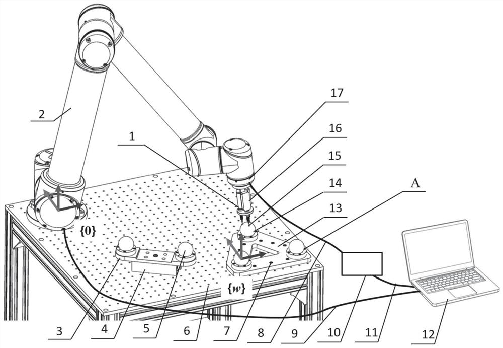
[0088]One aspect of the embodiment of the present invention provides an industrial robot step-by-step calibration system, which can be foundFigure 1A-Figure 1B As shown, it includes a movable double ball device 3, a fixed three-tension device 7, a terminal measuring device 1, a computer 12, a counter 10, and the like.

[0089]Further, the duplex apparatus 3, the three club device 7, and the base of the robot 2 are provided on the table of a table 6. Further, the double ball device 3 can be moved relative to the robot 2 base and is locked in any designated position within the robot 2 operating space, and the three-tension device 7 is relatively fixed with the robot 2 base.

[0090]Further, the double ball device 3 can be mounted on the table 6 of the magnetic stand 4, which i...


PUM


Abstract

The invention discloses an industrial robot step-by-step calibration system and method. The calibration system comprises a tail end measuring device arranged on a robot flange, as well as a movable double-ball device, a fixed three-ball-seat device, a counter, a computer and the like which are matched with a robot. The calibration method comprises first-step calibration: calibrating kinematics parameters of the robot by using a wide-area distance error; and second-step calibration: based on the result of the first-step calibration, calibrating the pose of a robot-based coordinate system by using a position error. Furthermore, the calibration method can also comprise the following steps: firstly, calibrating the measurement error of the tail end measurement device; and then carrying out the first-step calibration and the second-step calibration. The calibration system has the advantages of being portable, low in cost and the like; meanwhile, the calibration method improves the precision and reliability of kinematics calibration, calibration of the robot-based coordinate system is achieved, then the absolute positioning precision of the robot is improved, and the application range of the robot in precision manufacturing is widened.

Description

Technical field[0001]The present invention relates to a method of determining a robot, and more particularly to an industrial robot human step-by-step calibration system and method, at least for realizing a wide area calibration of the robot's body's motion parameters and a standard of robotic base, which belongs to robotics. Calibration field.Background technique[0002]At present, industrial robots typically have higher repetitive positioning accuracy, but its absolute positioning accuracy is low, which constrains the application of robots in the fields of precision manufacturing. This is mainly caused by the manufacturing, installation and wear error of industrial robots, leading to the actual motion parameters of robots deviate from the theoretical value preset in the robot controller, resulting in a decrease in the absolute positioning accuracy of robots. The robotic kinematics is an effective method for improving the absolute positioning accuracy of robots.[0003]In addition, the...

Claims


Application Information

Patent Timeline
Patent Type & Authority Applications(China)
IPC IPC(8): B25J9/16
CPCB25J9/1692B25J9/1653B25J9/161
Inventor 杨桂林谷乐丰方灶军张驰郑天江熊次远刘强
Owner NINGBO INST OF MATERIALS TECH & ENG CHINESE ACADEMY OF SCI
Why Eureka
Try Eureka