Film tearing mechanism, film tearing equipment and film tearing method

A technology of equipment and film disc, applied in the field of film tearing mechanism, can solve the problem of large consumption of tape, and achieve the effect of strong stickiness and lower production cost

Pending Publication Date: 2021-05-28
东莞工至科技有限公司
View PDF0 Cites 2 Cited by
  • Summary
  • Abstract
  • Description
  • Claims
  • Application Information

AI Technical Summary

Problems solved by technology

[0004] The purpose of the present invention is to provide a film tearing mechanism, film tearing equipment and film tearing method to solve the problem of excessive tape consumption of the current film tearing equipment

Method used


Image

  • Film tearing mechanism, film tearing equipment and film tearing method
  • Film tearing mechanism, film tearing equipment and film tearing method
  • Film tearing mechanism, film tearing equipment and film tearing method

Examples


Embodiment 1

[0049] The tearing film structure provided in this embodiment is mainly used in the scene of tearing the battery film, and can perform the film tearing process on sheets with films such as batteries and screens. The tearing film structure in this embodiment has the advantage of high tape utilization. features.

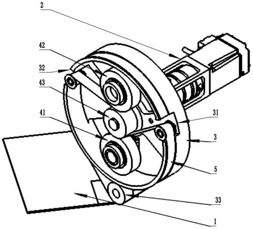
[0050] Such as figure 1 , Figure 4 to Figure 6 As shown, the film tearing mechanism of this embodiment includes a film tearing station 1 for placing sheet materials.

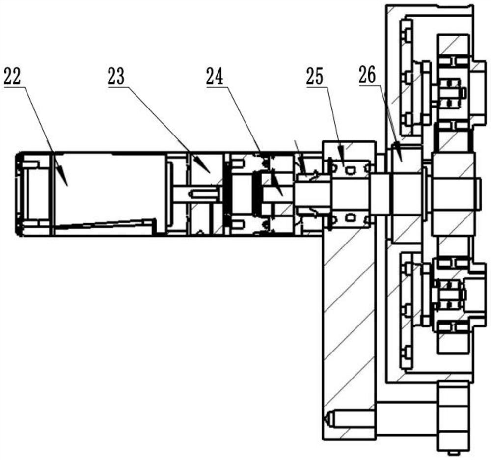
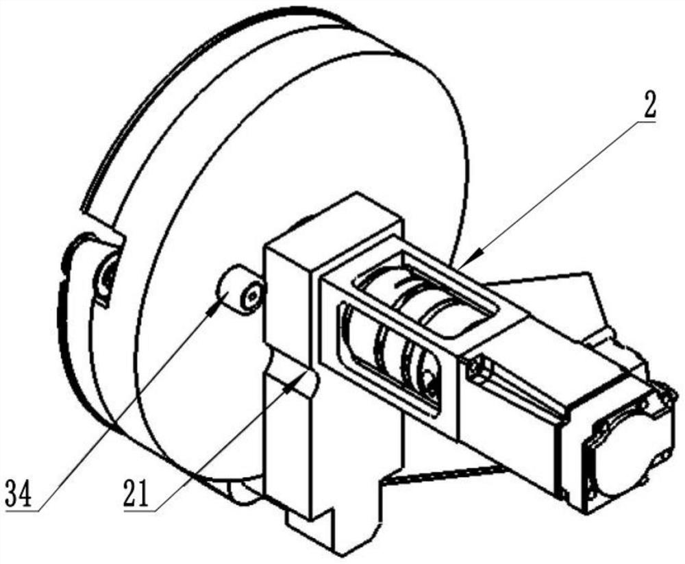
[0051] One side of the film tearing station 1 is provided with a rotating device 2 , and a film tearing disc 3 is installed on the rotating end of the rotating device 2 .

[0052] A mounting groove is formed in the tearing film disc 3 , a first winding device and a second winding device are arranged on the groove bottom of the mounting groove, and an adhesive tape 5 is wound on the first winding device.

[0053] A first glue outlet 31 and a second glue inlet 32 ​​are provided on the outer sidewall of...

Embodiment 2

[0074] Such as Figure 7 As shown, the film tearing device includes a conveying mechanism and a film tearing mechanism as in Embodiment 1.

[0075] The conveying mechanism is used to transport the plate to the film tearing station 1 of the film tearing mechanism.

Embodiment 3

[0077] A film tearing method, applied to the film tearing device as in embodiment two; specifically comprising:

[0078] S1, transport the sheet to the film tearing station, so that the film on the sheet is adhered by the new adhesive tape 51;

[0079] S2. Rotate the rotating device 2 along the first direction by a preset first angle; wherein, the first glue outlet 31 is rotated by the first angle along the direction away from the film tearing station 1, and the adhesive tape 5 is along the opposite direction of its extending direction The first length is pulled by the first glue outlet 31 .

[0080] Further, in step S2: rotate the rotating device 2 along the first direction by a preset first angle; wherein, the first glue outlet 31 is rotated by the first angle along the direction away from the film tearing station 1, and the adhesive tape 5 is rotated along its After the first length is pulled by the first glue outlet 31 in the opposite direction of the extension direction,...


PUM


Abstract

The invention discloses a film tearing mechanism, film tearing equipment and a film tearing method, and relates to the technical field of battery production. When film tearing is carried out on a plate, a rotating device is firstly made to drive a film tearing disc to rotate by a preset first angle in the first rotating direction, the first rotating direction refers to the direction opposite to the extending direction of an adhesive tape, the first angle comprises two stages, the first stage is a film lifting angle, and the second stage is a film tearing angle; when the rotating device rotates by the film lifting angle, an adhesive tape tensioned on a first extrusion roller is a new adhesive tape, the viscosity is high, and the film lifting efficiency can be guaranteed; and then, the rotating device drives the film tearing disc to continuously rotate the film tearing angle in the first rotating direction, and due to the fact that the first rotating direction is equal to the extending direction of the adhesive tape, the old adhesive tape is pulled to the first extrusion roller, that is, the old adhesive tape is used for separating the remaining film from the plate, the film tearing process is completed, the old adhesive tape is fully utilized, the environment-friendly effect is achieved, and the production cost is reduced.

Description

technical field [0001] The invention relates to the technical field of battery production, in particular to a film tearing mechanism, film tearing equipment and a film tearing method. Background technique [0002] The battery is an important part commonly used in people's daily life. Usually, the battery is provided with a film, which is attached to the upper and lower sides of the battery. Before using the battery, the film on the surface of the battery needs to be torn off. In the past, manual film tearing was usually used, but manual film tearing has the problem of occupying labor resources, so the mechanical automation of film tearing process is the development trend. [0003] In the film tearing equipment in the prior art, the tape is set on the battery through driving parts such as cylinders. After the film is adhered, the tape is driven by the driving part to move to separate the tape from the battery. However, this film tearing method leads to the use of The amount ...

Claims


Application Information

Patent Timeline
Patent Type & Authority Applications(China)
IPC IPC(8): B65B69/00
CPCB65B69/00
Inventor 郝启明周辉胡正米广辉杨维敏
Owner 东莞工至科技有限公司
Why Eureka
Try Eureka