Rolled glass edge adjusting device
An adjustment device and glass edge technology, which is applied in glass production, glass forming, glass rolling, etc., can solve the problems of easy-to-fry glass plates, low glass yield, and large trimming width, so as to improve the yield, Effect of improving thickness uniformity and improving service life
- Summary
- Abstract
- Description
- Claims
- Application Information
AI Technical Summary
Problems solved by technology
Method used
Image

Examples
Embodiment 1
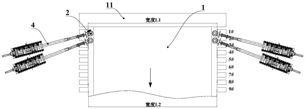
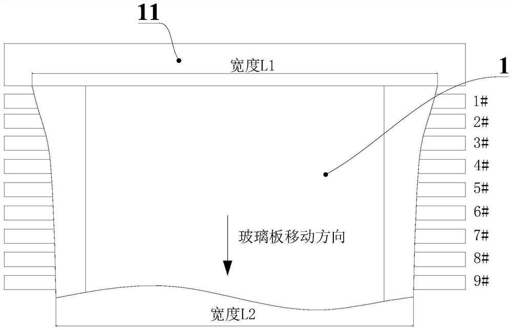
[0046] like figure 1 As shown, the present embodiment provides a rolling glass edge adjusting device. At least one adjusting wheel 2 is respectively arranged on both sides of the rolling glass 1 surface, and the adjusting wheel 2 is in contact with the surface of the rolling glass 1. The direction of rotation is opposite to that of rolling glass.
[0047] In this embodiment, the adjusting wheel 2 is reversely rotated on both sides of the surface of the rolled glass 1 to prevent the rolled glass from shrinking toward the middle, and promote the edge area of the rolled glass to maintain the same thickness as the middle area. At the same time, the edge of the rolled glass will not shrink. Obtain a larger net plate width and improve the yield of rolled glass production.
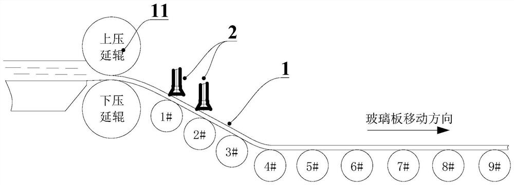
[0048] combine figure 2 Since the edge shrinkage of the rolled glass 1 mainly occurs in the area behind the calender roll 11, the adjusting wheel 2 is arranged behind the calender roll 11 and close to the ca...
Embodiment 2
[0059] refer to Image 6 The difference between this embodiment and Embodiment 1 is that a water-cooled tank 34 is also provided on the rotating tube 31. Since the cooling water needs to flow from the top to the bottom of the rotating tube 31 to cool the adjustment wheel 2, during this process Long-term contact between water and return water will affect the cooling effect. Based on this, in this embodiment, a water cooling box 34 is installed on the rotating tube 31 to cool the incoming water and return water again, so as to improve the cooling effect of the regulating wheel 2 .
[0060] combine Figure 7 , the rotating pipe 31 and the water cooling box 34 freely cooperate along the circumferential direction, the bottom of the water cooling box 34 is provided with a water inlet pipe 341, and the upper part is provided with a water outlet pipe 342, and the cooling medium flows from the water inlet pipe 341 through the outer wall of the rotating pipe 31 and then from the water o...
Embodiment 3
[0064] The difference between this embodiment and Embodiments 1 and 2 is that the rotating tube 31 is also fixedly provided with a rotating gear 345 located in the cooling cavity 343 eh, and along the radial direction of the rotating tube 31 is provided with a gear that passes through the surface of the water cooling box 34 and extends to the cooling chamber. The drive shaft 35 inside the cavity 343, the end of the drive shaft 35 towards the rotating tube 31 is fixed with a drive gear 351 meshing with the rotation gear 345, the drive shaft 35 is connected to the water cooling box 34 through a second bearing 352, Similarly, a waterproof sealing ring is provided between the drive shaft 35 and the water-cooled box 34 as required.
[0065] The end of the drive shaft 35 away from the rotating tube 31 can be directly connected to a driving mechanism such as a motor to drive, and the driving gear 351 is perpendicular to the direction of the axis of rotation of the rotating gear 345, p...
PUM
 Abstract
Description
Claims
Application Information
 - R&D Engineer
- R&D Manager
- IP Professional
- Industry Leading Data Capabilities
- Powerful AI technology
- Patent DNA Extraction
Browse by: Latest US Patents, China's latest patents, Technical Efficacy Thesaurus, Application Domain, Technology Topic.
© 2024 PatSnap. All rights reserved.Legal|Privacy policy|Modern Slavery Act Transparency Statement|Sitemap