Vaporized fuel oil furnace

An oil-fired furnace and fuel oil technology, applied in the burner, combustion method, combustion type and other directions, can solve the problems of incomplete fuel vaporization, high production cost, high maintenance cost, and achieve fast vaporization speed, short vaporization time and convenient use. Effect

CN112856401AActive Publication Date: 2021-05-28邓光勇 +2
5 Cites 0 Cited by

Patent Information

Authority / Receiving Office
CN · China
Patent Type
Applications(China)
Current Assignee / Owner
Publication Date
2021-05-28

Smart Images

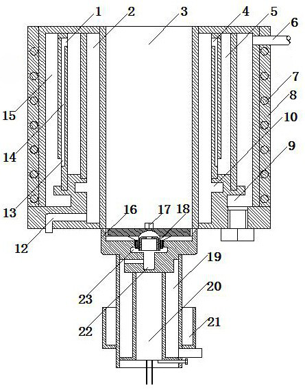
  • Figure 1
    Figure 1
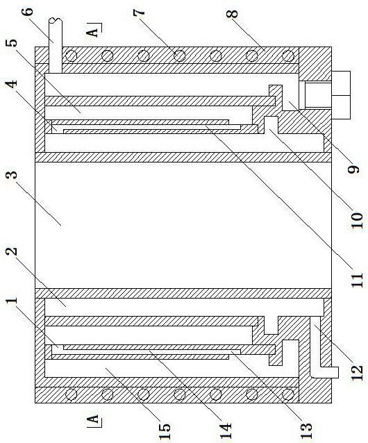
  • Figure 2
    Figure 2
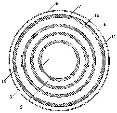
  • Figure 3
    Figure 3
Patent Text Reader

Abstract

The invention discloses a vaporized fuel oil furnace which comprises a furnace body and a furnace end, and the furnace body comprises a combustion cavity, a vaporization cavity and an electric heating device; the vaporization cavity comprises a primary cavity and a final-stage cavity, and the electric heating device is arranged around the final-stage cavity and is electrically connected with a power supply; the furnace end comprises a fire spraying sleeve and a fire spraying head; the fire spraying sleeve is provided with a placing cavity for placing the fire spraying head in a sleeving manner; the fire spraying head comprises a splitter plate, a guide cavity and an adjusting cylinder; the splitter plate is sealed at the top of the placing cavity; the splitter plate is provided with an air injection sub-runner and a flow guide hole; the outlet of the air injection sub-runner points to the combustion cavity, and inlets of the air injection sub-runner communicates with the placing cavity; the flow guide hole is formed in the bottom of the splitter plate, and two ends of the flow guide hole communicate with the guide cavity and the placing cavity respectively; and the lower bottom of the adjusting cylinder is open, the upper bottom of the adjusting cylinder is sealed and is provided with a vent hole, the upper end of the adjusting cylinder is arranged in the guide cavity and is in threaded connection with the inner wall of the guide cavity, and the lower end of the adjusting cylinder communicates with a communicating cavity, so that the flow of the alcohol-based steam transmitted from the guide cavity to the flow guide hole is adjusted.
Need to check novelty before this filing date? Find Prior Art

Description

technical field

[0001] The invention relates to a combustion stove, in particular to a gasification fuel burner. Background technique

[0002] Alcohol-based fuel (methanol fuel) has the advantages of low fuel consumption, much higher firepower than liquefied petroleum gas, more economical use, safety, and environmental protection. It is widely used in hotels, restaurants, guesthouses, school canteens, fast food, restaurants, etc. Alcohol-based gasification combustion furnaces have also gradually developed.

[0003] Currently used vaporized fuel burners, because the temperature in the furnace body vaporization chamber is generally below 120°C, resulting in incomplete vaporization of the fuel, resulting in incomplete combustion of the vaporized fuel in the furnace; when the purity of alcohol-based fuel is lower than 70% or in a cold environment In winter, especially when the temperature in the north is below -10°C, the preheating and vaporization of alcohol-based fuel takes a...

Examples

Embodiment Construction

[0058] The present invention is described in detail below in conjunction with accompanying drawing and specific embodiment:

[0059] Such as figure 1 , figure 2 , image 3 , Figure 4 , Figure 5 , Figure 6 , Figure 7 , Figure 8 , Figure 9 As shown, the gasification fuel burner of the present invention includes a furnace body and a burner head. The furnace body includes a combustion chamber 3, a vaporization chamber and an electric heating device. The vaporization chamber includes a primary chamber 2 and a final chamber 15 . The primary chamber 2 is arranged around the combustion chamber 3, and the bottom of the primary chamber 2 is provided with an inlet 12 communicating with vaporized fuel. The final cavity 15 is arranged around the primary cavity 2 and communicated with the primary cavity 2 , and the vaporized fuel outlet 6 is provided on the top of the final cavity 15 . The lower side wall of the primary chamber 2 is preferably provided with an annular carb...