
Method for calculating transfer function of cabin of wind turbine

A technology of nacelle transfer function and calculation method, which is applied in the field of wind turbine nacelle transfer function calculation, can solve the problems of inability to guarantee the accuracy of free-flow wind speed derivation, large randomness and uncertainty, and strict requirements for the configuration site, and achieves the application Rich scenes, reduced computational cost, and low computational cost

Active Publication Date: 2021-05-28
CHINA THREE GORGES CORPORATION
View PDF6 Cites 3 Cited by
  • Summary
  • Abstract
  • Description
  • Claims
  • Application Information

AI Technical Summary

Problems solved by technology

The method is simple and easy to use, but relies heavily on mast data
Since China's wind power layout adopts a "large-scale, high-concentration" model, a single wind farm often contains dozens or even hundreds of wind turbines, and the configuration of wind towers is demanding and expensive, so usually only one of them is selected. A typical wind turbine is equipped with a wind measuring tower for characteristic evaluation, which cannot meet the needs of all wind turbines in the whole site
For the correction of engine room wind speed of many other atypical units, this method has great randomness and uncertainty, and cannot guarantee the accuracy of free flow wind speed derivation

Method used


Image

  • Method for calculating transfer function of cabin of wind turbine
  • Method for calculating transfer function of cabin of wind turbine
  • Method for calculating transfer function of cabin of wind turbine

Examples


Embodiment Construction

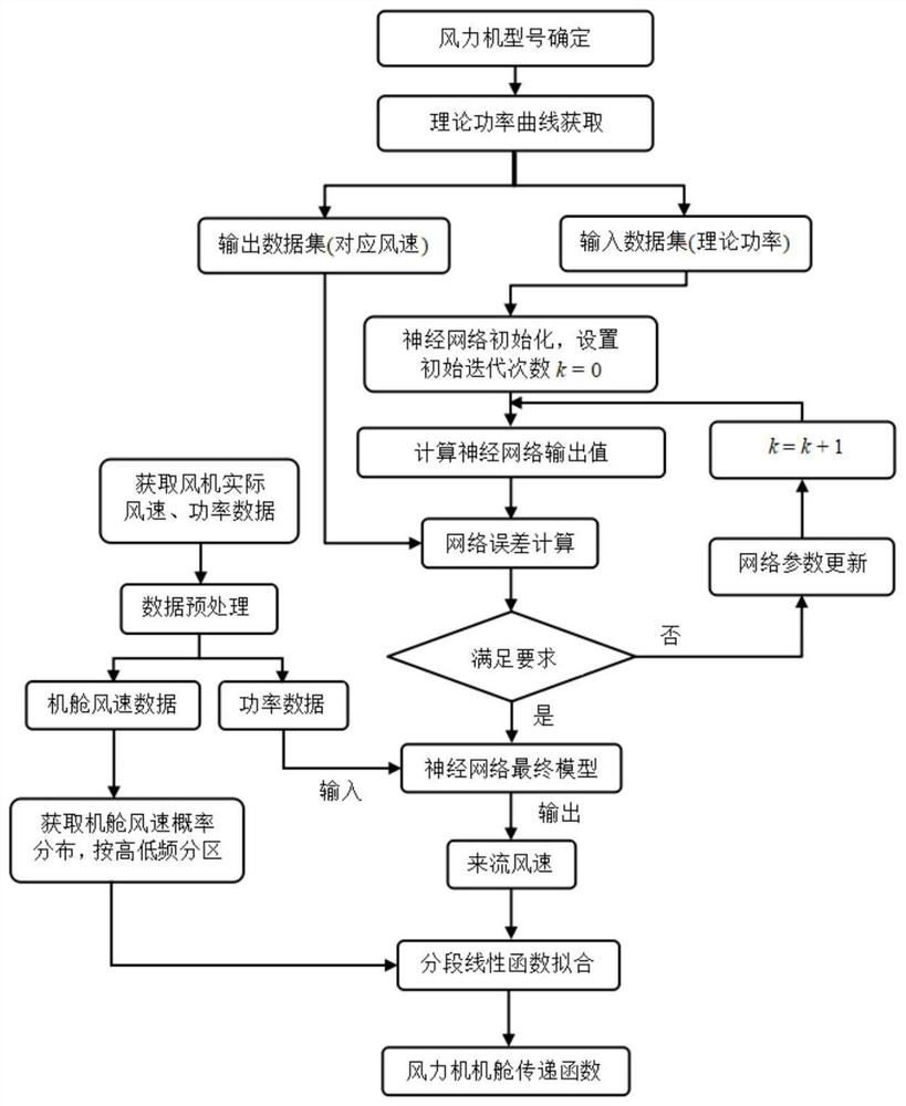
[0041] A method for calculating a transfer function of a wind turbine nacelle, comprising the following steps:

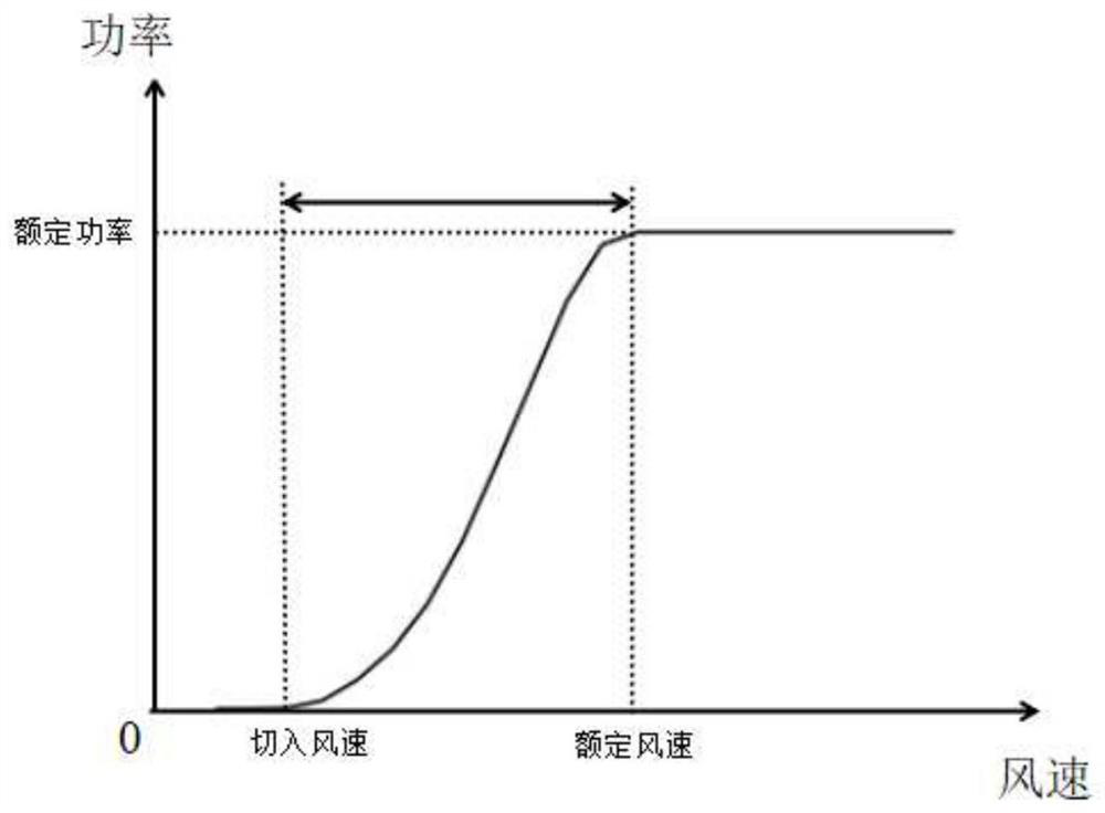
[0042] Step 1: For a single wind turbine in the selected wind farm, obtain its theoretical power curve by consulting the product manual of the corresponding manufacturer's model of the wind turbine, and calculate it according to zero wind speed-cut-in wind speed, cut-in wind speed-rated wind speed, rated wind speed-cut-out wind speed The three ranges of wind speed are divided into three sections, and the area between cut-in wind speed and rated wind speed is selected to obtain the theoretical power curve of the fan, such as figure 2 shown.

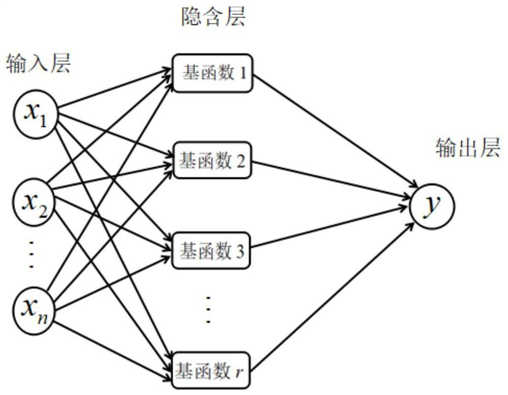
[0043] Step 2: Adopt image 3 The neural network shown in the figure reverses the theoretical power curve of the fan. The input of the neural network is the theoretical power value, and the output is the corresponding wind speed. The neural network adopts the error backpropagation algorithm, which mainly obtains the optimal v...


PUM


Abstract

A method for calculating a cabin transfer function of a wind turbine comprises the following steps: acquiring a theoretical power curve of a single fan, and selecting an area between cut-in wind speed and rated wind speed; adopting the neural network to carry out backward deduction on the area, and inputting wind power data from an actual operation wind power plant into the trained neural network to obtain a corresponding incoming flow wind speed value; acquiring cabin wind speed data in one-to-one correspondence with the wind power data, and dividing the cabin wind speed data into a high-frequency region and a low-frequency region; and performing partition processing on the high-frequency region and the low-frequency region respectively; in each interval, carrying out linear function fitting on the cabin wind speed and the corresponding incoming flow wind speed, and forming a cabin transfer function of the fan according to the linear function fitting. The wind turbine cabin transfer function calculation method has the advantages of being high in fitting precision and small in calculation amount, and is suitable for wind turbine incoming flow wind speed calculation and wake flow evaluation.

Description

technical field [0001] The invention relates to the technical field of wind power generation, in particular to a method for calculating a transfer function of a wind turbine nacelle. Background technique [0002] In the process of power generation calculation, economic benefit evaluation, unit layout optimization, and operation optimization control in wind farms, it is usually necessary to carry out modeling work on the wake effect of wind turbines. Currently, commonly used wake assessment models mainly include computational fluid dynamics models and analytical models. Accurate acquisition of free-flow wind speed is an important prerequisite to ensure the accuracy of such models. Aiming at the problem that the free-flow wind speed is not easy to measure directly, wind farms usually default the wind speed of the nacelle to the incoming wind speed, and do not distinguish between the two. However, due to factors such as the rotation of the wind rotor and the airflow distortio...

Claims


Application Information

Patent Timeline
Patent Type & Authority Applications(China)
IPC IPC(8): G06F30/27G06N3/08G06F119/14
CPCG06F30/27G06N3/084G06F2119/14Y02E10/72
Inventor 张皓易侃张子良王浩
Owner CHINA THREE GORGES CORPORATION
Learn More