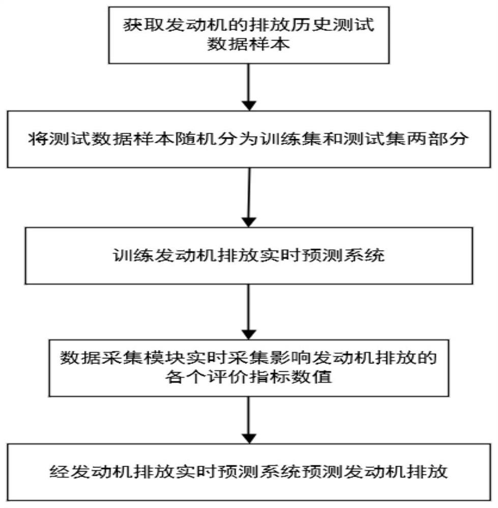
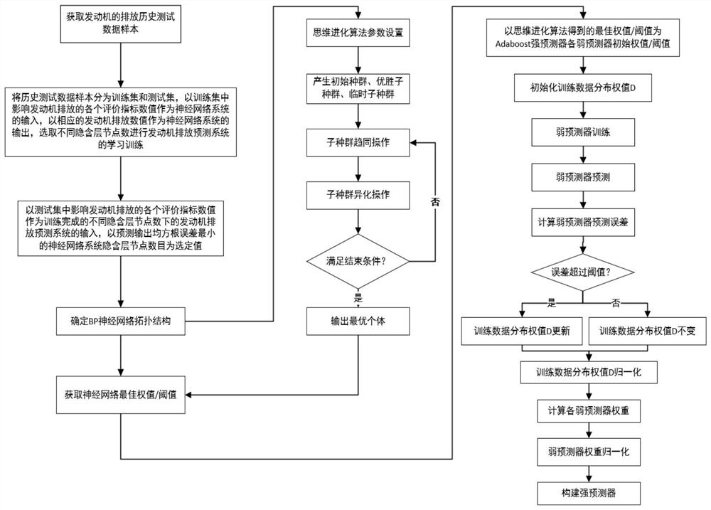
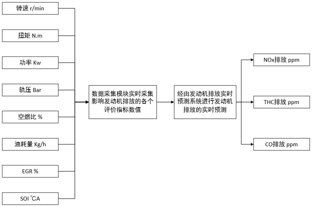
Real-time prediction method for engine emission

A real-time prediction and engine technology, which is applied in the direction of engine testing, internal combustion engine testing, neural learning methods, etc., can solve the problems of not reflecting the engine's transient emission performance well, long calculation time, expensive instrument purchase and maintenance costs, etc. , to achieve the effect of improving the efficiency of the algorithm, accurate prediction results, and avoiding limited generalization ability

Inactive Publication Date: 2021-05-28
TIANJIN UNIV
View PDF6 Cites 5 Cited by
  • Summary
  • Abstract
  • Description
  • Claims
  • Application Information

AI Technical Summary

Problems solved by technology

However, these two methods have certain limitations. The first method needs to simulate the extremely complex physical and chemical reactions of the engine combustion, and needs to build a detailed three-dimensional mesh model of the engine. The accuracy of the emission simulation results is largely Calculation time is lengthy due to mesh density and quality
However, the gas analyzers and other instruments used in the second method are greatly affected by environmental factors, cannot reflect the transient emission performance of the engine well, and most of them can only provide accurate emission values ​​within a certain limited range. In the process, it is often necessary to build a complete set of supporting equipment, and the purchase and maintenance of related instruments are expensive

Method used


Image

  • Real-time prediction method for engine emission
  • Real-time prediction method for engine emission
  • Real-time prediction method for engine emission

Examples


Embodiment approach

[0084] As an embodiment of the present invention, the specific steps are:

[0085] Step 4021, define the individual score function of each winning subpopulation and temporary subpopulation, the steps are:

[0086] First, each individual in each winning subpopulation and temporary subpopulation is decoded to obtain the neural network connection weight matrix and threshold matrix corresponding to each individual. The steps are:

[0087] Transform the first to p*g elements of each subpopulation into the first connection weight matrix w in the order of columns p×g , that is, the first column of the matrix is ​​filled first, and then the other columns are filled in turn, each element in the first connection weight matrix and the connection weight from the input layer neuron to the hidden layer neuron in the step 3 value w ks Consistent; transform the p*g+1th element to the p*g+g*hth element of the individual into the second connection weight matrix w in the order of columns g×h ...

Embodiment

[0117] Select 100 groups of engine emission history test data samples, randomly select 90 groups of samples to train the prediction model adopted in the engine emission real-time prediction method proposed by the present invention, and use the remaining 10 groups of samples as a test set to check the accuracy of the method of the present invention ,get:

[0118] 1. The NOx emission prediction effect of the engine emission real-time prediction method proposed by the present invention and the neural network without any optimization and only through the initial weight threshold optimization is shown in the figure Figure 5 shown;

[0119] 2. The real-time prediction method of engine emission proposed by the present invention is compared with the relative error of the NOx emission prediction value of the neural network without any optimization and only through the initial weight threshold optimization. Image 6 shown;

[0120] 3. The comparison of the THC emission prediction eff...


PUM


Abstract

The invention discloses an engine emission real-time prediction method, which comprises the following steps of: firstly, acquiring a plurality of known engine emission historical test data samples, dividing the samples into a training set and a test set to train a neural network, and calculating neural network output root-mean-square errors under different hidden layer nodes to determine a neural network topological structure; and then the initial weight and threshold of the neural network are optimized through a mind evolutionary algorithm, and finally an engine emission real-time prediction system is established by using an Adaboost algorithm. The problems that an existing engine emission data acquisition mode wastes time and labor, is limited by environmental factors, is high in instrument cost, is poor in transient emission measurement performance and the like are solved, and the transient emission data of the engine can be measured only by simply measuring the rotating speed, torque, power, track pressure, air-fuel ratio, oil consumption, EGR (exhaust gas recirculation) rate and SOI (oil injection time) in the operation process of the engine. Therefore, transient NOx emission, THC emission and CO emission of the engine can be accurately predicted in real time.

Description

technical field [0001] The invention relates to engine exhaust emission detection, in particular to a real-time engine emission prediction method. Background technique [0002] At present, there are two main ways to obtain engine emission data. One is to simulate the combustion process in the cylinder of the engine with the help of CFD software, and the other is to measure engine emissions through gas analyzers and other instruments in the engine bench test. However, these two methods have certain limitations. The first method needs to simulate the extremely complex physical and chemical reactions of the engine combustion, and needs to build a detailed three-dimensional mesh model of the engine. The accuracy of the emission simulation results is largely Affected by mesh density and quality, calculation time is lengthy. However, the gas analyzers and other instruments used in the second method are greatly affected by environmental factors, cannot reflect the transient emissi...

Claims


Application Information

Patent Timeline
Patent Type & Authority Applications(China)
IPC IPC(8): G06F30/27G06N3/04G06N3/08G06F111/10
CPCG06F30/27G06N3/086G06F2111/10G06N3/045G01M15/05G01M15/102G06F18/24133G06F18/214
Inventor 刘海峰张晓腾王灿尧命发
Owner TIANJIN UNIV
Why Eureka
Try Eureka