Connector
A connector and threaded connection technology, which is applied in the direction of connection, two-part connection device, and parts of the connection device, can solve the problems of affecting the reuse of the connector, affecting the service life of the connector, low melting temperature, etc. The effect of processing and production, simple and reasonable structure, and prolonging the service life
- Summary
- Abstract
- Description
- Claims
- Application Information
AI Technical Summary
Problems solved by technology
Method used
Image

Examples
Embodiment 1
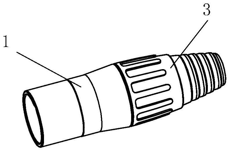
[0031] Such as Figure 3-7 As shown, a stainless steel connector includes a shell, a tail sleeve 3 and an inner core assembly 4. The outer shell is formed by connecting the outer stainless steel shell 1 and the front section of the inner core shell 2 through a fixed structure, wherein The stainless steel shell 1 is made of stainless steel pipe or stainless steel rod, which is machined and turned, and has high hardness and is not easy to deform. The inner core shell 2 is formed by die-casting of a zinc alloy mold. The front section of the inner core housing 2 is a cylindrical plug-in section 21 that is plugged and assembled with the rear end of the stainless steel shell 1, and the rear section of the inner core housing 2 is an external thread connection section 22 connected with the tail sleeve 3. The sleeve 3 and the inner core housing 2 are fixed through threaded connection.
[0032] The outer diameter of the plug-in section 21 of the inner core shell 2 in this embodiment is...
Embodiment 2
[0035] Such as Figure 8 , 9 As shown, the difference from Embodiment 1 is that the connection mode between the inner core shell 2 and the stainless steel shell 1 is different, and this embodiment adopts a spring-type fixing structure.
[0036] The specific structure is as follows: a diameter-reducing step 20 is provided between the rear end of the plug-in section 21 of the inner core housing 2 and the threaded connection section 22, and a card is recessed on the inner wall of the rear opening of the stainless steel housing 1. Spring slot 11, a snap ring 5 is arranged in the snap ring slot 11, the insertion section 21 of the inner core shell 2 is inserted into the stainless steel shell 1 and fixed by the snap spring 5 against the step surface.
Embodiment 3
[0038] Such as Figure 10 , 11 As shown, the difference from Embodiment 1 is that the connection mode between the inner core shell 2 and the stainless steel shell 1 is different, and this embodiment adopts a buckle-type fixing structure.
[0039] The specific structure is as follows: the outer peripheral surface of the plug-in section 21 of the inner core housing 2 is provided with at least one buckle 24, the inner wall of the stainless steel housing 1 is concavely provided with a corresponding buckle groove 12, and the inner wall of the inner core housing 2 is provided with a buckle 24. The inserting section 21 is inserted into the stainless steel housing 1 and fixed through the cooperation of the buckle 24 and the buckle groove 12 .
[0040] Preferably, there are two buckles 24, which are respectively arranged symmetrically on the upper and lower sides of the outer peripheral surface of the inserting section 21 of the inner core housing 2. Correspondingly, the inner wall of...
PUM
 Abstract
Description
Claims
Application Information
 - R&D Engineer
- R&D Manager
- IP Professional
- Industry Leading Data Capabilities
- Powerful AI technology
- Patent DNA Extraction
Browse by: Latest US Patents, China's latest patents, Technical Efficacy Thesaurus, Application Domain, Technology Topic.
© 2024 PatSnap. All rights reserved.Legal|Privacy policy|Modern Slavery Act Transparency Statement|Sitemap