Parasitic power generation unit of photovoltaic power station and power generation method

A technology of power generation unit and photovoltaic power station, which is applied in the direction of photovoltaic power generation, support structure of photovoltaic modules, photovoltaic modules, etc., can solve the problem that light irradiation resources cannot be effectively used, and achieve reduction of land use area, cost reduction, and simple structure Effect

Pending Publication Date: 2021-05-28
丁慈鑫 +2
View PDF0 Cites 4 Cited by
  • Summary
  • Abstract
  • Description
  • Claims
  • Application Information

AI Technical Summary

Problems solved by technology

[0004] The current design and layout of photovoltaic arrays has a large space area between the net distances. The light radiation resources corresponding to this part of the land area are usually not effectively utilized. If it can be developed and utilized, it is very meaningful

Method used


Image

  • Parasitic power generation unit of photovoltaic power station and power generation method
  • Parasitic power generation unit of photovoltaic power station and power generation method
  • Parasitic power generation unit of photovoltaic power station and power generation method

Examples


Embodiment 1

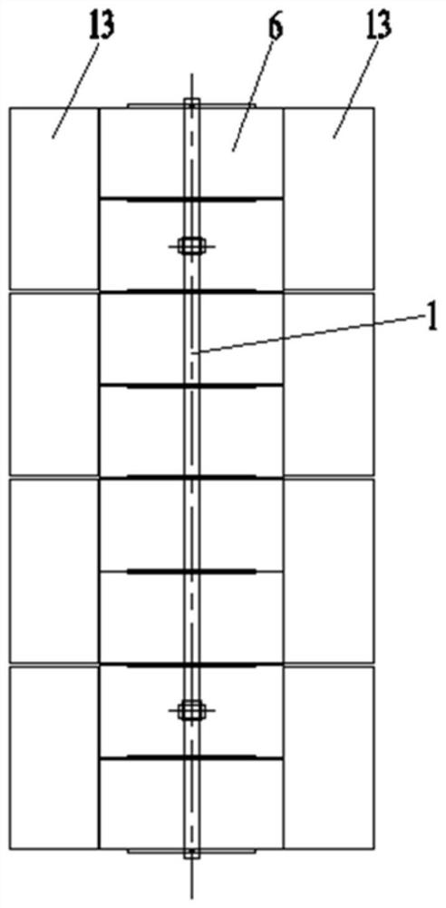
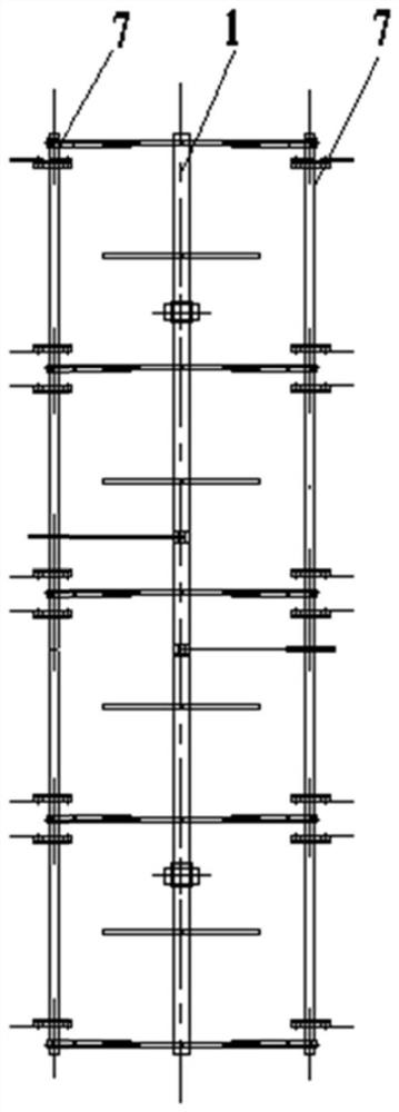
[0077] Such as Figure 10 and Figure 11 , the main body bracket 1 is a flat single-axis tracking bracket, and the light radiation receiving plate 13 will move together with the flat single-axis tracking bracket. Figure 10 The movement process of the folding wing support 7 following the flat single-axis tracking support is shown.

[0078] Figure 11 The movement process of the light radiation receiving plate 13 of the folding wing support 7 to avoid wind is shown. In this embodiment, the light radiation receiving plate 13 is a photovoltaic module board. When the folding wing bracket 7 is sheltered from the wind, the rotating drive mechanism drives the light radiation receiving plate 13 to rotate, so that the light radiation receiving plate 13 is in the same state as the photovoltaic module board 6 of the main body bracket 1, and rotates to a state perpendicular to the photovoltaic module board 6. Then turn to the bottom of the photovoltaic module board 6 and be parallel to...

Embodiment 2

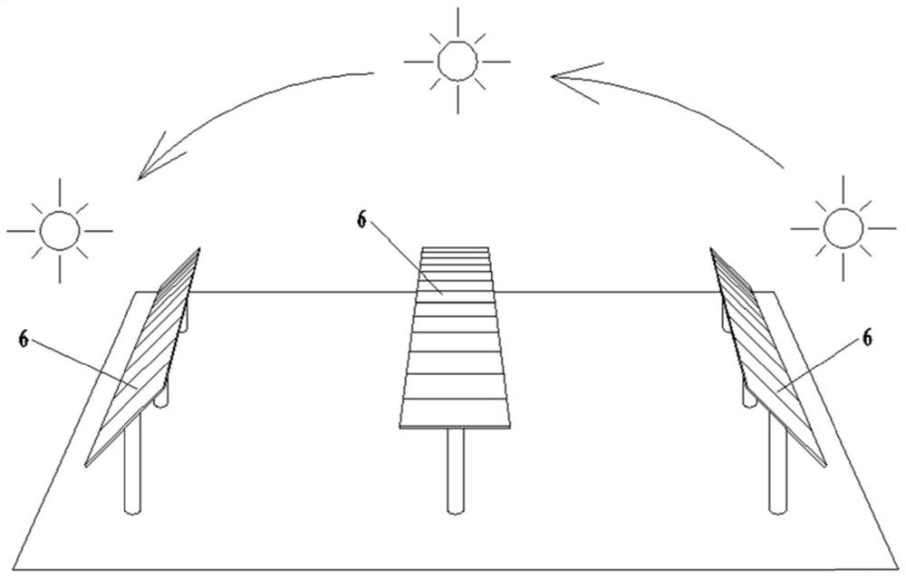
[0084] Such as Figure 12 , generally, the light radiation receiving plate 13 of the folding wing support 7 is flush with the photovoltaic module plate 6 of the fixed inclination angle support. Further, the inclination angle of the light radiation receiving plate 13 can be properly adjusted to track changes in the sun's elevation angle and azimuth angle to improve power generation capacity, and it can be deployed and retracted in real time according to functional requirements, scene conditions, and design performance. In this embodiment, glass mirror reflectors cannot be installed, and only photovoltaic module boards can be installed. For the module boards with the same power, the single Wp annual power generation of the photovoltaic module board will exceed the single Wp annual power generation of the fixed inclination main support. Especially in the summer half year, this is a peculiar phenomenon with unexpected surprise effects. Similarly, according to functional requirem...

Embodiment 3

[0090] Such as Figure 17 , is a schematic diagram of the installation position of the folding wing bracket 7 attached to the oblique single-axis tracking bracket, and the folding wing bracket 7 is installed on both sides of the oblique single-axis tracking bracket. In this embodiment, the light radiation receiving plate 13 may be a glass mirror reflective plate, or a photovoltaic module plate. For the module boards with the same power, the single Wp annual power generation of the photovoltaic module board is slightly less than the single Wp annual power generation of the oblique single-axis tracking main frame. Similarly, according to functional requirements, scene conditions, and design performance, it is deployed in real time to receive light radiation and retracted inward to avoid strong wind loads and shadow effects between adjacent arrays. In this embodiment, the folded wing support 7 is installed on the oblique uniaxial tracking support to generate power, which can inc...


PUM


Abstract

The invention relates to a parasitic power generation unit of a photovoltaic power station and a power generation method. The power generation unit comprises a folding wing support attached to a main body support, the top of the main body support is provided with a photovoltaic assembly plate, and the folding wing support comprises a connection beam fixedly connected with parallel beams in the same direction in the main body support. A rotating shaft support is arranged at the end, away from the main body support, of the connection beam, a rotating shaft is arranged in the rotating shaft support, a light irradiation receiving plate is fixed to the rotating shaft, and the rotating shaft and the light irradiation receiving plate are driven by a rotating driving mechanism to rotate. When the light irradiation receiving plate rotates to be flush with the photovoltaic assembly plate or form a certain angle with the photovoltaic assembly plate, power generation is carried out to make unavailable light energy converted into available energy, so that the installed capacity of a photovoltaic power station can be greatly increased under the condition that the land area is not increased or slightly increased; and when the light irradiation receiving plate rotates to the position under the photovoltaic module plate, the light irradiation receiving plate is folded for wind sheltering, so that strong wind weather can be avoided in real time, and a wind sheltering state can be quickly entered.

Description

technical field [0001] The invention relates to the technical field of photovoltaic power generation, in particular to a parasitic power generation unit and a power generation method of a photovoltaic power station. Background technique [0002] my country started the construction of photovoltaic power plants on a large scale in 2010, and entered the stage of canceling state subsidies and grid parity in 2018. 2021 is the first year of comprehensive grid parity. On October 23, 2020, the National Energy Administration approved the "Code for Photovoltaic Power Generation System Efficiency" (NB / T 10394-2020). The capacity ratio is about 1.2, the best capacity ratio in the second type of area is about 1.4, and the best capacity ratio in the third type area can reach up to about 1.8. This will effectively promote the process of grid parity for photovoltaic power generation across the country. [0003] Therefore, a large number of old power stations urgently need to carry out tec...

Claims


Application Information

Patent Timeline
Patent Type & Authority Applications(China)
IPC IPC(8): H02S20/32H02S40/22H02S30/20F24S30/425F24S50/20
CPCF24S30/425F24S50/20H02S20/32H02S30/20H02S40/22Y02E10/47Y02E10/52
Inventor 丁慈鑫丁宁丁树东
Owner 丁慈鑫
Why Eureka
Try Eureka