Clamp with repeated clamping function for numerical control machine tool

A CNC machine tool and clamping technology, which is applied in the direction of the chuck, etc., can solve the problems of troublesome adjustment process, difficult adjustment, and affecting the coaxiality of the processing surfaces at both ends of the part, and achieve the effect of high practicability and elimination of jumping

Pending Publication Date: 2021-06-01
武汉中鸿森电器有限公司
View PDF0 Cites 7 Cited by
  • Summary
  • Abstract
  • Description
  • Claims
  • Application Information

AI Technical Summary

Problems solved by technology

[0003] At present, the processing of shaft parts in machine tools generally requires one clamping to complete the processing. If multiple clampings are required, the coaxiality of the front and rear ends of the part must be judged by the experience of the tool and the staff in the subsequent clamping. , and then to ensure the machining accuracy; when clamping, if repeated clamping and correction are performed, the change of the clamping position after re-clamping and the wear of the clamping parts at the front and rear ends of the part due to the previous clamping may affect the part. The coaxiality of the processing surfaces at both ends, especially for parts with a certain length, and when re-clamping, the adjustment process is often troublesome and difficult to adjust

Method used


Image

  • Clamp with repeated clamping function for numerical control machine tool
  • Clamp with repeated clamping function for numerical control machine tool
  • Clamp with repeated clamping function for numerical control machine tool

Examples


Embodiment Construction

[0033] The specific implementation manners of the present invention will be further described in detail below in conjunction with the accompanying drawings and embodiments. The following examples or drawings are used to illustrate the present invention, but not to limit the scope of the present invention.

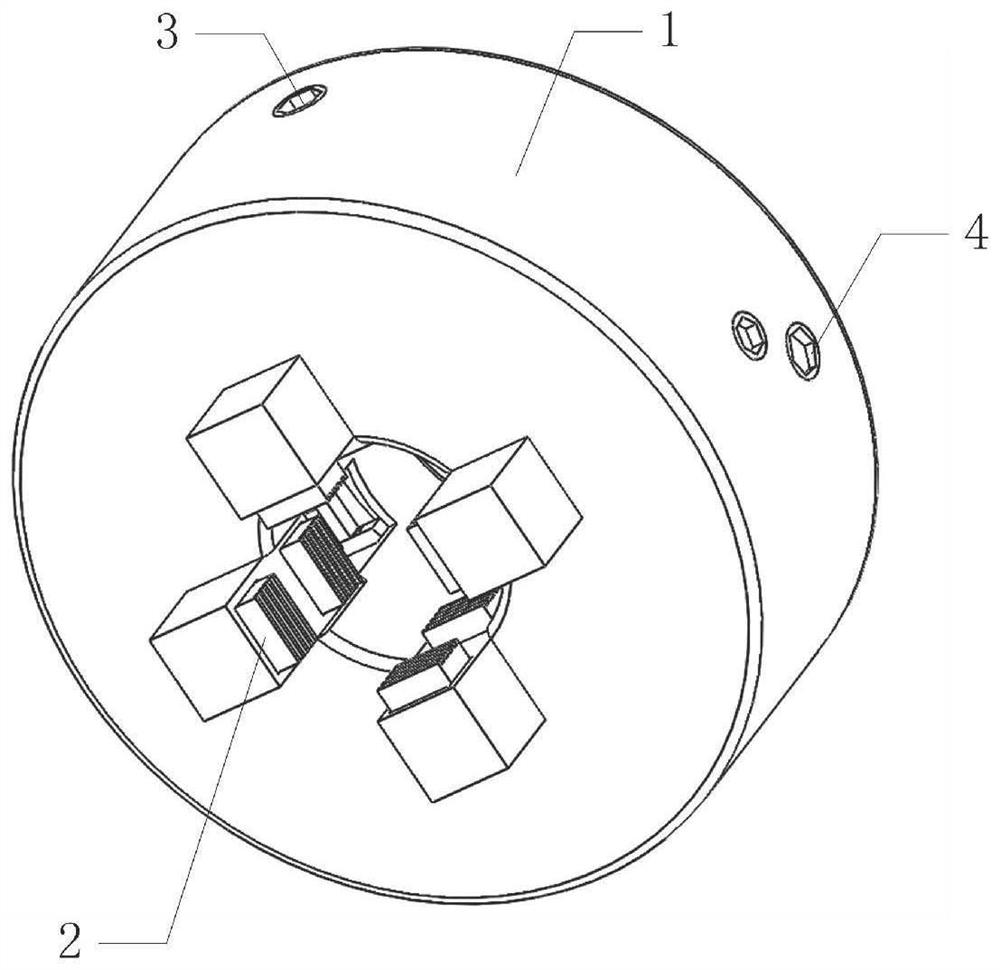
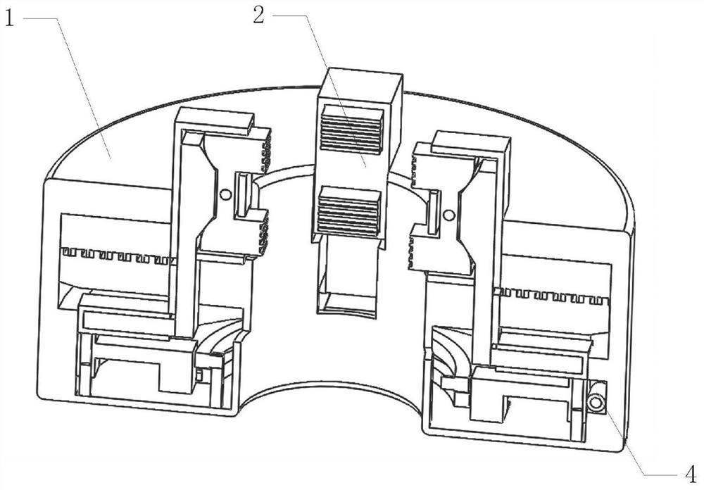
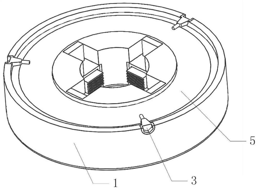
[0034] Such as figure 1 , 2 As shown, it includes a chuck 1, a claw mechanism 2, a first adjustment rod 3, and a coil wire 5, wherein as figure 2 , 3 , 7, the coil wire 5 is rotatably installed in the chuck 1, the adjusting rod has teeth, the three first adjusting rods 3 are evenly rotated in the circumferential direction and installed on the chuck 1, and the three first adjusting rods 3 The upper teeth mesh with one end of the coil wire 5 having teeth, and the claw mechanism 2 is installed on the chuck 1; four claw mechanisms 2 are evenly installed on the chuck 1 in the circumferential direction. The coil wire 5 and the first adjusting rod 3 designed by the present in...


PUM


Abstract

The invention belongs to the technical field of machine tool clamps, and particularly relates to a clamp with a repeated clamping function for a numerical control machine tool. The clamp comprises a chuck, clamping jaw mechanisms, first adjusting rods and a coiled wire. According to the designed clamp, during adjustment, firstly, eight clamping blocks in four clamping jaws slightly clamp a workpiece by driving one of the three first adjusting rods, but a spindle can drive the workpiece to rotate through the clamp under the clamping force, but the clamping force is not clamping force during turning work, a worker can observe the installation condition of the workpiece under the clamping force to judge whether the workpiece jumps or not, then each adjusting mechanism is controlled to adjust two adjusting blocks on the corresponding side according to the jumping condition, then the adjusting blocks extrude two corresponding clamping jaws, and four clamping blocks in the two clamping jaws adjust the installation state of the workpiece upwards or downwards or leftwards or rightwards through respective swinging, so that the final machining precision of the workpiece is guaranteed.

Description

[0001] Technical field [0002] The invention belongs to the technical field of machine tool fixtures, in particular to a repeatable clamping fixture for a numerically controlled machine tool. Background technique [0003] At present, the processing of shaft parts in machine tools generally requires one clamping to complete the processing. If multiple clampings are required, the coaxiality of the front and rear ends of the part must be judged by the experience of the tool and the staff in the subsequent clamping. , and then to ensure the machining accuracy; when clamping, if repeated clamping and correction are performed, the change of the clamping position after re-clamping and the wear of the clamping parts at the front and rear ends of the part due to the previous clamping may affect the part. The coaxiality of the processing surfaces at both ends, especially for parts with a certain length, and when re-clamping, the adjustment process is often cumbersome and difficult to a...

Claims


Application Information

Patent Timeline
Patent Type & Authority Applications(China)
IPC IPC(8): B23B31/02B23B31/16B23B31/103
CPCB23B31/02B23B31/103B23B31/16
Inventor 方红艳张胜勇
Owner 武汉中鸿森电器有限公司
Why Eureka
Try Eureka