Small steel cutting plane device

A technology of small steel and chips, which is applied in the field of steel processing, can solve problems such as misreading numbers, burns of workers, and easy flying off of workpieces, etc., and achieves the effects of reasonable design, simple operation, and high finish

Pending Publication Date: 2021-06-01
惠州市三和兴实业有限公司
View PDF0 Cites 0 Cited by
  • Summary
  • Abstract
  • Description
  • Claims
  • Application Information

AI Technical Summary

Problems solved by technology

[0002] In the past, the processing of small steel materials required experienced workers to operate. On the milling machine, install a magnetic chuck and add two baffles. The workpiece must be carefully fixed on the magnetic chuck. During the processing, shake it manually. If the clamping is not good, the workpiece is easy to fly off, which is very dangerous, and it is easy to cause damage to the machine tools, especially if the flying off workpiece hits the worker, it is easy to cause physical damage to the worker, and in the process of processing, a lot of iron filings will be generated. However, most equipment The comparison effect is simple, there is no protective cover, it is easy to cause burns to workers, and the requirements for processed parts are also high, requiring a positive and negative difference between 0.1, often using micrometer calipers for measurement, and each material is different, It is easy to misread the number and make wrong steel materials. Sometimes there are too many workpieces, and workers need to work overtime. Long-term overtime makes workers physically unbearable

Method used


Image

  • Small steel cutting plane device
  • Small steel cutting plane device
  • Small steel cutting plane device

Examples


Embodiment Construction

[0019]The technical solutions of the present invention will be described below in conjunction with the drawings, as will be described, as described herein is an embodiment of the invention, not all of the embodiments. Based on the embodiments of the present invention, there are all other embodiments obtained without making creative labor without making creative labor premises.

[0020]In the description of the invention, it is to be described in the terms "center", "upper", "lower", "left", "right", "vertical", "horizontal", "within", "outside", etc. The orientation or positional relationship indicated is based on the orientation or positional relationship shown in the drawings, is merely intended to describe the present invention and simplified description, rather than indicating or implying that the device or component must have a specific orientation. Construct and operation, so it is not understood to be the limitation of the invention. Moreover, the term "first", "second", "third"...


PUM


Abstract

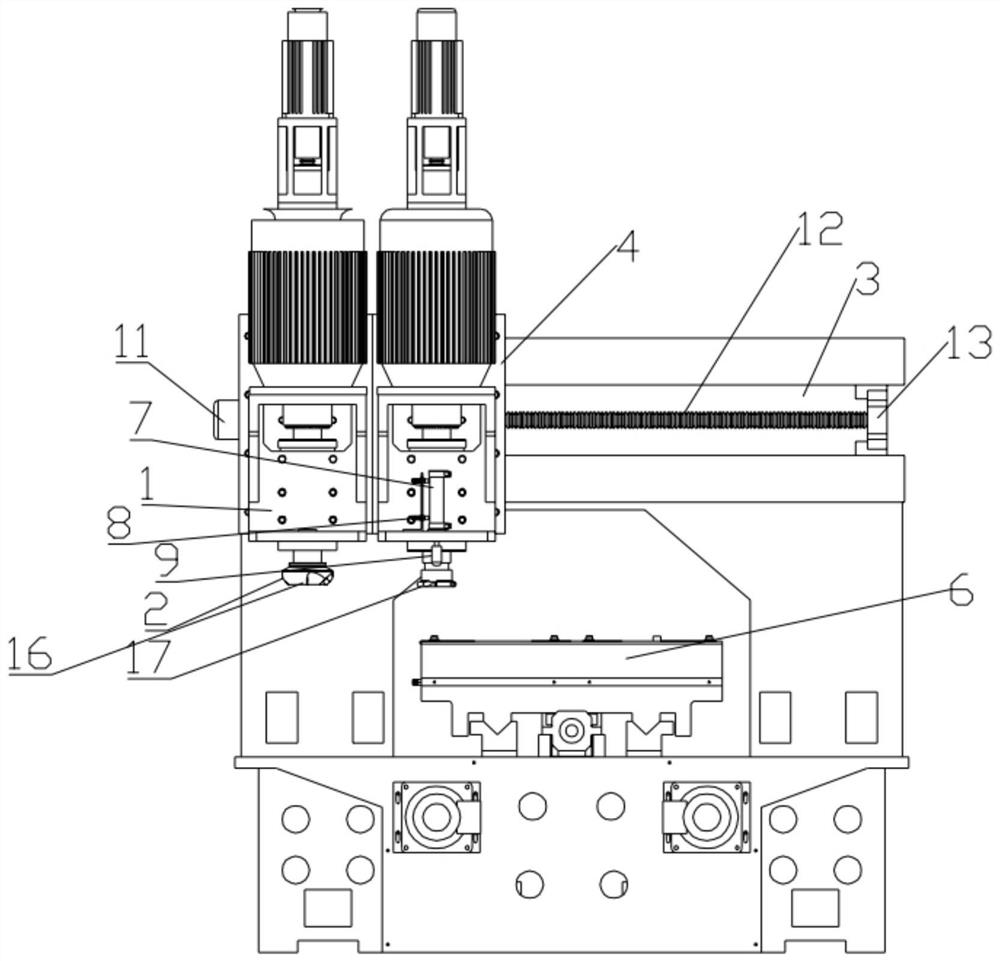
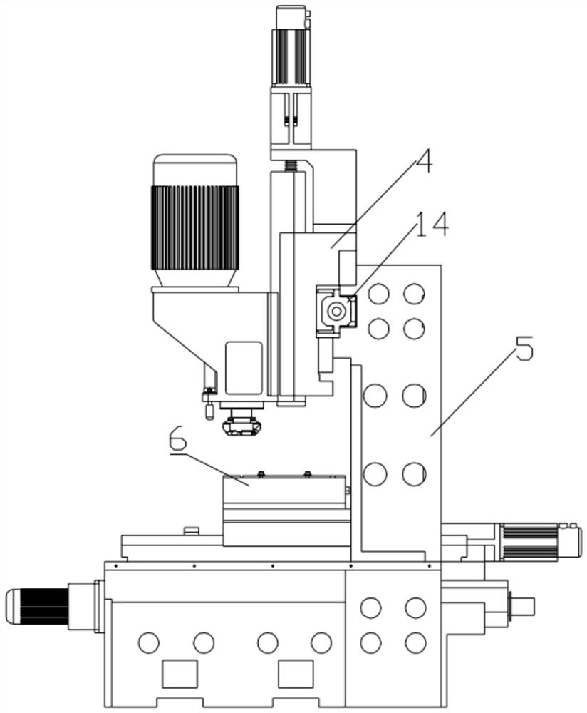
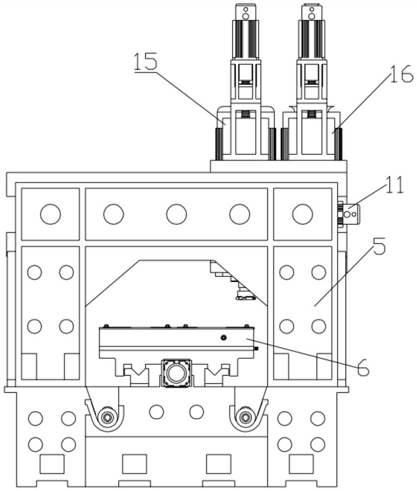
The invention discloses a small steel cutting plane device which comprises a cutting device, a cutting head, a driving assembly, a baffle, a fixing piece and a clamping and fixing device, wherein the clamping and fixing device is arranged on the fixing piece, the driving assembly is arranged on the fixing piece, the baffle is arranged on the driving assembly, the cutting device is arranged on the baffle, the cutting head is arranged on the cutting device, the cutting device is provided with an air cylinder, a magnetic sensor and a depth detection head, the air cylinder is arranged on the cutting device, the magnetic sensor is arranged on the cutting device and connected with the air cylinder, the depth detection head is connected with the air cylinder, and a magnetic ring is arranged in the air cylinder. The invention belongs to the technical field of steel machining, and specifically relates to a small steel cutting plane device suitable for various machine tools.

Description

Technical field[0001]The present invention belongs to the technical field of steel processing, and is specifically a small steel chip planar device.Background technique[0002]In the past, small steels needed to have experienced workers to operate, put on a milling machine, loaded with a magnetic suction cup, plus two baffles, and the workpiece should be carefully fixed on the magnetic suction cup. During the machining process, The clamp is not good, the workpiece is very easy, very dangerous, easy to cause damage to the machine tool, especially afraid of flying workpieces to hit workers, easy to cause the worker's body damage, and during processing, there will be a lot of iron filings, but most equipment Diffusion, no shield occlusion, easy to cause workers burns, and the requirements for processing parts are also high, requiring positive and negative differences between 0.1, often using thousands of caliper, and each material is different, It is easy to appear wrong, do something wr...

Claims


Application Information

Patent Timeline
Patent Type & Authority Applications(China)
IPC IPC(8): B23C1/08B23Q3/06B23Q5/40B23Q17/22
CPCB23C1/08B23Q3/06B23Q5/40B23Q17/2233
Inventor 黄国林
Owner 惠州市三和兴实业有限公司
Why Eureka
Try Eureka